
Loading...
Loading...
Loading...
Loading...
Loading...
Loading...
Loading...
Loading...
Loading...
Loading...
Loading...
Loading...
Loading...
Loading...
Loading...
Loading...
Loading...
Loading...
Loading...
Loading...
Loading...
Loading...
Loading...
Loading...
Loading...
Loading...
Loading...
Loading...
Loading...
Loading...
Loading...
Loading...
Loading...
Loading...
Loading...
Loading...
Loading...
Loading...
Loading...
Loading...
Loading...
Loading...
Loading...
Loading...
Loading...
Loading...
Loading...
Loading...
Loading...
Loading...
Loading...
Loading...
Loading...
Loading...
Loading...
Loading...
Loading...
Loading...
Jump right in and create your first game asset by following one of our tutorials! We recommended you start with these tutorials first, as the other tutorials build off knowledge from these tutorials.
🌐Creating Static Meshes💥Creating Static Collisions🎸Creating PropsIt's also highly recommended that you check out the documentation section. There you will find detailed information about each file type and how it is represented in Blender.
🌐Drawables (.ydr)When picking a building it is a good idea to have some thoughts for what you want to make. When it's your first time make an interior it is a good idea to make a single or double roomed interior.
Start by opening CodeWalker and find the building you want to make an interior inside.
For this tutorial I have chosen this building from grapeseed.
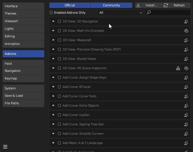
Starting with Blender 4.2, Sollumz can now be installed as an extension from our repository https://repo.sollumz.org/.
First, add https://repo.sollumz.org/ as a remote repository by navigating to Preferences > Get Extensions > Repositories > + > Add Remote Repository:
Next, search for "Sollumz". You will see two available versions to install:
Sollumz: The official release version, identical to what can be downloaded from the release page.
Sollumz (Development): The latest development build, which may be unstable. Use this version to test new features and updates, and provide feedback to help us improve.
Choose your preferred version and click Install:
Once installed, you can easily update to newer versions directly within Blender. You will see an Update button whenever new versions are available.
Download Sollumz.zip from the .
Open Blender, go to Edit > Preferences > Add-ons
Click Install... and select the downloaded zip file.
Now enable the add-on by checking the checkbox.
Restart Blender.
This part is optional but a good idea for bigger interiors
When planning you can do a lot you can use Photoshop, Paint, or anything to draw what you want this do not have to be to scale. This is also a good time to make mood boards find out what you want the building be like and the art style modern, old, western, etc.
This is some floor plans I have made for interiors they are not beautiful, but they are a way to stay on target.
Now we need a collision so the player can walk inside the interior without falling through the walls and floor. Let's start with opening of the building collision.
Go and show every ybn that are where there is a doorway and edit it so there is a hole inside to the interior. Remember to take the camera inside the interior to see if there is any collision that needs to be moved/deleted.
Like that we now have removed the collision so the players actually can go inside the interior.
A basic understanding of modding in GTA V including using CodeWalker.
Blender 4.0 or later - blender.org
Latest version of CodeWalker found in #releases channel. Download
If you think you've found a bug or you wish to request a feature, please use the issue tracker on GitHub. Be sure you extensively troubleshoot the issue first to ensure a bug is actually present.
Join the discord and be a part of our growing community!


If you have any questions, feel free to ask on our Discord server. Please use the "help" channel.
Helpers are taking time out of their day to help you, so please make an effort to provide as much detail as possible in your post. See the pinned post "How to ask questions" for guidelines on how to ask questions.
The easiest way to do it is to make a copy of the shell and then convert it to a ybn, but before you just convert then export you'll need to assign the material so the footsteps and gun shots wil behave as intended.
To make a copy of the shell just press SHIFT+D and then right click and then ALT+P move the duplicated shell out of the drawable so it can be made to a ybn.
Now that we have made a copy it needs to be converted to a Composite you do that by marking the mesh and pressing V and selecting the option convert to Composite and then the option Apply flag preset
You are now ready to assign the material to the collision. Here you just need to find the material that is closest to what material you have chosen on the drawable, and then it's just assign them the same way as the texture.
The floor material need to be different for each room so the room ID can be set to the material


A mesh located at the world location (where you want the collision to be)
The first thing to do is apply location transforms on your object(s). Select all the objects and press CTRL + A and select 'Location'.
Next go to Sollumz Tools > Collisions > Create Bounds and select your object(s) and click 'Convert to Composite'.
Ensure that the Bound Composite and Bound GeometryBVH empties are located at 0, 0, 0.
Next, Center the origins of your object(s), go to Object > Set Origin > Origin to Geometry.
It should now look something like this.
Last step is to rename the 'Bound Composite' empty to your .ybn file name.
Using Primitive shapes such as, 'Bound Poly Box', 'Bound Poly Capsule', 'Bound Poly Sphere' should be used for majority of your collisions, unless the mesh is a complex shape and cannot be made up of multiple primitive shapes. This is because it is more performance friendly and reduces unnecessary asset size.


When you have found the building and selected it, copy the name from the right hand side and search in the files using the RPF Explorer from the tool menu
To export from CodeWalker we need the xml file before you export it you can open the file to ensure it is the right one, and we get that by right-clicking and pressing export to xml.
To get every texture use the >> to find the textures and save them to the folder of the building name so when we load the model into Blender we don't have any missing textures.
This is also the time to find everything you will need. A little hint is you need everything you are going to modify and the ground around the building as it is really easy to create the floor to collide or texture fight. To find every file that is in the area right-click on the file again and press open file location, here you can find the ground every decal and other tings from the area, in this folder you can find .ydr (drawables) .ytd (textures), .ybn ( collisions), .yft (fragments), and the .ymf (manifest)
The easiest way to find the collisions is to open them from the RPF explore and export every .ybn that have anything with the building you are making to do. NOTE: It is important to take the hi@[name].ybn and the [name].ybn. The reason they are split up is because of the way GTA collisions work, the hi@ is for example for bullet so when a player shoots the building the bullet hits where the building and gets the right bullet hole and sound, the other one is example the player collision so when the player walks into the building they don't just walk through it. But in real life this is nothing you should be worried about unless you make major modifications to an exterior of a building.
The .ymap is the last file that is needed to be exported from CodeWalker the .ymap file have a lot of information that we can use to our advantage, some of the information in this file are the cords so we can place the buildings and decal at their exact locations. There can be more than one .ymap file so be sure that you have every .ymap file.
To find the .ymap name can be done in a couple of ways if you are making a small building you can look in the information menu to the right
If there are more .ymap files it can be easier to open a new project select everything that is going to be modified and read the name of the .ymap name
You should now have a folder that look something like this if you only exported the building and collisions. I wil now go ahead and export the building decals so when it is imported into Blender it will look more like the game this is optional but if you will edit them you should just export it from CodeWalker now, but you can always import later so no worries.
To start with you only import the ybn and ydr files not the ymap files and then the ymap file after
I have chosen to use the file hierarchy ydr ybn and ymap this is just a way to separate the files and not necessary you can use whatever you'd like to have you can think of it as folders
When you have imported everything you can open the ymap file and find a copy of the building you have imported you can go to it by pressing NUM, Keybindings may vary
This is to make it much easier to model. We can make it so that our mesh have the orientation of the building we are trying to make an interior inside of.
To do this we select an area that is the closest to the orientation in this tutorial the roof was the closest, so you selected the roof and pressed shift + NUM7 and to get the 3D cursor over you first go out of edit mode and then presses shift + mouse2 (Right mouse button) before adding Mesh Plane, click n to open Right panel and click the View tab remove rotation from the 3d cursor on X and Y Axis you then go up and adds a plane from mesh and in the menu down to the left press Align -> 3D cursor, and now you have the mesh to build the floor and walls of, and it is in the right orientation and now to get back to the normal view press NUM5. Once again keybindings may vary
We now need to set the model to the world origin, but we don't just set it back but make a mirror and send the original back to world origin. To make a mirror of the object we selected just press ALT+D and then right click cancel movement of the mirrored object. Now that we have a copy of the model. We can unparent it with ALT+P and click "Clear and Keep Transformation". Then select the original, not the model but the empty and clear transformation with ALT+R and ALT+G. You'll now have the model at the location and at the world origin. The mirror will be used to get the location so when we need to create the ymap it will be at the exact same place as in blender you can therefore rename the mirror to "Location" or whatever you want it doesn't really matter what the name is.
Now it is time to actually model your interior the plane we made before is the starting point and build out from that so you ensure that the orientation will follow for this tutorial I will just make a very simple 2 room interior
Now I have made the floor of the 2 room and removed the doors
Now add some walls
And add the roof
This part is the most time-consuming this step can be merged a bit together with the texturing but for this tutorial we will have it operated for better overview. This is also where you edit the decals and other thing you want to edit.
When you have your model you need to convert it to a drawable. To convert your object(s) to a Drawable. Select all the objects and click Convert to Drawable in Sollumz Tools > Drawable > Create Drawable Objects.
If you navigate to Mesh Properties > Sollumz LODs you'll also notice that the active mesh is automatically assigned to the "High" LOD level. This panel is where you can assign other meshes as LODs. More info on that . For the sake of this tutorial, we will only be setting the High LOD level.
When making an interior there are about 9 steps to take.
Picking a building
Importing from CodeWalker
Planning
Modeling
Interior
Decals
Other props
Exterior
Texturing
Vertex coloring
Collision
Creating ytyp
Rooms/Portals
Exporting from Blender
Creating ymap
This is not the only order to make an interior every step, can be made when you want to or are ready to. Every step is as a tutorial in the headline in itself.
Basic Blender skills ()
There will be some tips in this tutorial
Know how to either stream assets in a FiveM server or load mods into the base-game
This tutorial is a minimal way to make an interior, so I will not go over things like making doors and moving objects this is purely how to make an interior.
Let's start at the beginning and pick a building you want to make an interior in.
To export you just need to select every item you want to export and open Sollumz tool and press export. Note that the object need to be visible to be exported so make sure that everything you want to export is not hidden.
We now need to convert the xml to gta formats we do that by opening the RPF Explorer and then open a folder you want the files to be in and drag the xml file into the RPF Explorer.
Not every file type found in GTA is supported by Sollumz.
Next, we need to add materials to the Drawable Models. With one of the Drawable Models selected, open the Sollumz Tools > Drawable > Shader Tools panel. For this tutorial, I will use the "NORMAL" shader which allows us to specify a base color and a normal map. Search for the "NORMAL" shader and click Create Shader Material.
To add a texture open shader tool and find the normal one select your drawable and then pres Create Shader Material, and it should appear in the Material menu in this tutorial I make 1 set of textures for each room so each room have a roof, wall, and floor. In this sample I use the normal, but you can play around with the others they have some different attributes that can be useful
With the newly added material selected, head to the material section then open Sollumz > Texture Parameters then press the folder icon and select the texture you want.
So now we have a somewhat finished model now it is time to make the archetype (.ytyp). The archetype is a file that contains information about the model, collision, and texture it is also in the file we determine how many rooms there are and where the portals between rooms are and entities in the room (This can be easier to do in CodeWalker later on), it is also time to create the map data (.ymap) this is where we place exterior entities and in the interior we defined in the archetype. There are ways to do it directly inside of Blender, but it is not part of this tutorial check out if you want to know more.
Start by opening Sollumz Tools > Archetype Definition > YTYPS and then press the + icon to create a new archetype then you can mark every item you have made just the drawable then make sure it is set to base then press Auto-Create From Selected then mark the collision change to MLO and then press Auto-Create From Selected again you now have the definition of every drawable and the MLO where the portals are defined.
Decals
Other props
Modifying terrain
Create the ybn


TODO
TODO
TODO
Lights are well, lights that are embedded into .ydr or .yft objects. there is many different settings for these lights which can make it very tricky and confusing to get right.
z_z_alien.yft
z_z_fred.yft
z_z_fred_large.yft
z_z_wilma.yft
z_z_wilma_large.yft
a_c_boar.yft
a_c_cat_01.yft
a_c_chickenhawk.yft
a_c_chimp.yft
a_c_cormorant.yft
a_c_cow.yft
a_c_coyote.yft
a_c_crow.yft
a_c_deer.yft
a_c_dolphin.yft
a_c_fish.yft
a_c_hen.yft
a_c_humpback.yft
a_c_killerwhale.yft
a_c_pig.yft
a_c_pigeon.yft
a_c_poodle.yft
a_c_pug.yft
a_c_rabbit_01.yft
a_c_rat.yft
a_c_rhesus.yft
a_c_seagull.yft
a_c_sharkhammer.yft
a_c_stingray.yft
a_c_westy.yft
a_c_whalegrey.yft
a_c_chop.yft
a_c_husky.yft
a_c_mtlion.yft
a_c_retriever.yft
a_c_rottweiler.yft
a_c_sharktiger.yft
a_c_shepherd.yft
a_c_chimp_02.yft
a_c_rabbit_02.yft
a_c_panther.yft
a_c_chickenhawk.yft
a_c_rhesus.yft
a_c_seagull.yft
a_c_chop_02.yft
a_c_chickenhawk.yftWhen selecting textures you'll need to make sure their resolution is power of 2 E.g. 16x16 32x16 512x512 512x16.
It also needs to be .dds and not jpg, png, or any other file format.
When you have set a texture open the UV Editing tab where you can edit the placement of the texture if the textures is placed wild you have to select the textures right click and press the Unwrap button
There are 2 way to store the textures in a ytd (texture dictionary) or embedded in the model. There are reasons to use either, but I won't come into when to use what for this tutorial i wil just use the embedded way. Chose each texture from the menu and press the Set all Textures Embedded button
To set the vertex paint open Data > Color Attributes and add a new color attribute called Color 1 and it need to be set to Face Corner and Byte Color for this tutorial I will just use green at .2 and everything else at 0 the vertex coloring is something you can play around with.
Red control ambient occlusion of the model during night, most (except for night lights) will have it topped to 255 so it gets very dark at night
Green artificial light, topping this to 255 will give a self emissive power to the object. Used for objects near to lampposts or light sources to simulate ambient lightning
Blue moonlight illumination, how much the object reflects of the moonlight. Rockstar uses this at very frequent situations to avoid a fully dark atmosphere

Now we want to create the rooms for every room + limbo, first select the mlo and open the tab Rooms now we add the first room witch is the limbo room it is created by pressing the Create Limbo Room, now the rest of the rooms will be added by pressing the + foreach room you'll need in this tutorial, then we just need 2 one for the front room and one for the back room. Then to fit the room select the collision and open edit mode and select the 4 vertices and press the button Set Bounds From Selection
Now it is time for portals. Go to the Portals tab and mark the 4 corners of the doorway and make the portal from inside to outside, when inside it doesn't really matter what way they are facing. When the portal is set make sure the direction of the arrow in the portal faces the same way as the instructed and if not use the Flip Direction button to flip so the arrow match.
Now to add the shell as an entity, navigate to the Entities tab and select the drawable and press the Add Object(s) as Entity, and it will be added now just add the room limbo to the entity
We are now done with the archetype there are much more to know about the archetype you can read more about it here There is also much more to discover here you can play around with the timecycles and flags on room and portals these can also be done in CodeWalker
Bones can be easily moved in Edit mode. To move them:
Switch to Solid Mode
Toggle X-Ray
Choose a bone you want to move
Select it in 3D View
Click on Move icon
Move the bone using gizmo.
All models rely on LOD meshes, which greatly reduces graphics demand of detailed models and improves overall performance.
if you have any other LOD meshes ready to be set up, copy their names to the proper LOD levels.
In order to render your mesh at any distance:
Go to Data tab.
Scroll to Sollumz LOD.
Copy the name from High LOD to Very High, Medium and Low.
Key
🟩 Fully implemented
🟧 Partially implemented
🟥 Not implemented
Game meshes are stored in the file format. Creating Drawables in Sollumz is very simple. This tutorial will walk you through step-by-step.
The first thing to do is convert your object(s) to a Drawable. Select all the objects and click Convert to Drawable in Sollumz Tools > Drawables > Create Drawable Objects.
Fragments are objects that contain separable parts and react to physics. These objects are typically used in breakable props (i.e. street lamps) and vehicles. The file contains a Drawable and a Composite (collision), and sometimes multiple of each if there is a destroyed variant such as in gas tanks. However, Sollumz does not currently support editing destroyed variants of Fragments.
It's recommended that you read the documentation page on Drawables and collisions first, as Fragments are made up of these objects.
Paint colors allow you to determine which materials represent the Primary color, Secondary color, Wheel color, Interior Trim color, and Dashboard color. To select the paint color for a material, navigate to Material Properties > Sollumz > Fragment.
By default it will be "Not Paintable", meaning the shader will not be affected by any paint color.
In the Export Codewalker XML > Fragment panel, you will find the Toggle LODs option.
This allows you to export just the hi YFT, just the non-hi YFT, or both at the same time.


vehicle_paint


TODO
A model with textures prepared
From the CodeWalker RPF Explorer, open the asset with the textures.
Click the save icon in the top right, then click "Save All Textures"
In Blender, press the V key, then click Find Missing Files and select the folder where you saved the textures.
Alternatively, export all textures into a folder with the same name as the file you are importing. For instance, if you wanted to import adder.yft with all of its textures, you would export all textures to a folder called adder in the same directory. Then, when you import into Sollumz, all textures will be automatically loaded from the adder folder.
Make sure you generate a "_manifest.ymf" file from the CodeWalker project window with your MLO, YMAP, and YTYP in it.
9 out of 10 times it is due to having an outdated Sollumz version. Try updating.
No Sollumz objects in the scene to export! or No Sollumz objects selected for export!Check if the "Limit to Selected" export option is ticked. If so, only the selected objects will export.
Make sure all of your objects have their sollum type set, otherwise, they will not be recognized by the add-on.
As a last resort, you can select the parent object and use Sollumz Tools > General > Debug > Fix Hierarchy
Update your Sollumz.
One of your materials has a missing node connection between Color node and an Image Texture, which is 100% needed in order to export the model.
Check shading tab to find more.
Only the Principled BSDF shader is supported during material conversion operations, anything else must be converted or recreated using Principled BSDF as base.
Remember to apply General (default) flags to your Bound GeometryBVH object from the Sollumz Tools > Collision Tools > Flag Presets menu.
Since this plugin was designed around CodeWalker's XML file formats, OpenIV is not explicitly supported. You may experience issues going from Sollumz > CodeWalker > OpenIV. It's highly recommended that you just use CodeWalker.
Vertices in Blender and in game meshes have different meaning. For Blender, it is basically just a position. For the game, it is position + attributes (normals, colors, UVs, etc). Closer to what Blender calls "Face Corners".
Don't think Blender shows the number of face corners anywhere without python, but after triangulization, it is basically number of faces*3.
On export, Sollumz removes duplicate face corners when it can, when position and all its attributes are the same. So the final vertex count in the game mesh is somewhere between number of vertices and number of face corners.
Anyways, number of faces is more representative of the model quality/performance, so just use that, not vertices.
Check the UV Maps and Color Attribute names, they have to follow the Sollumz naming convention. Sollumz is warning a user when names don't match.
Make sure the "Import To Asset Library" checkbox is unchecked and try to import again.
Since this plugin was designed around CodeWalker's XML file formats, OpenIV is not explicitly supported. You may experience issues going from Sollumz > CodeWalker > OpenIV. It's highly recommended that you just use CodeWalker.
Drawable
.ydr.xml
🟩
🟩
Drawable Dictionary
.ydd.xml
🟩
🟩
Static Collision
Mesh editing
🟩
Embedded collisions
🟩
Shader editing
🟩
Terrain shader painting
🟩
Tint shaders
🟩
Editing Drawable Dictionaries
🟩
Importing with external skeleton
🟩
Collision editing
🟩
Vehicles
🟩
Breakable props (i.e. street lights)
🟩
Breakable glass props
🟩
Explodable props (i.e. gas tanks)
🟩
Ped yfts
🟥
Skeletal Animations
🟩
UV Animations
🟩
Camera Animations
🟩
Light Animations
🟧
Entities
🟩
Box Occluders
🟩
Car Generators
🟩
Model Occluders
🟩
Physics Dictionaries
🟥
Base Archetypes
🟩
Time Archetypes
🟩
MLO Archetypes
🟩
Create rooms from vertices
🟩
Create portals from vertices
🟩
If you navigate to Mesh Properties > Sollumz LODs with the drawable model selected, you'll also notice that the active mesh is automatically assigned to the "High" LOD level. This panel is where you can assign other meshes as LODs. More info on that here. For the sake of this tutorial, we will only be setting the High LOD level.

As the import has finished, you will see an imported mesh.
The subject of consideration for this tutorial is the bonnet part. To assign a material, go to Material tab, click on Browse material button and select the material from the list. In this case, I have assigned a vehicle paint one to the outer part of the bonnet.
The same is true for all the bonnet's materials.
The file layout for Fragments is quite complex, even with the simplified layout shown above (if you wish to see the full file layout, just open a yft.xml). However, you don't need to understand how the file works internally to understand how it works in Sollumz.
The Fragment contains a main Drawable as well as a Physics section which contains the collisions and physics data. PhysicsGroups contains groups of physics data where each group is linked to a bone. This is essentially the physics properties for each bone. PhysicsChildren contains physics data for each collision (i.e. mass, inertia). Each physics child belongs to a PhysicsGroup, and multiple children can belong to a single group.
You'll also notice there is a VehicleGlassWindows section. As the name implies, this is where data relating to vehicle windows are stored. Non-vehicle fragments can also have GlassWindows, but that is not currently supported by Sollumz.
Finally, there are Lights, which, just like Drawables, contain any lights that the Fragment might have (only ever used in prop Fragments).
The Blender hierarchy for Fragments is quite simple. The Fragment object itself is an armature with a Bound Composite and Drawable parented to it. The Fragment can also contain lights. Lights are typically stored in an empty object called "Lights", but can also be stored loosely in the Fragment or under the Drawable. It's up to you where to store the lights, as, during export, it will search all children (recursively) for lights. The hierarchy for the Bound Composite and Drawable is exactly the same.
Game meshes are stored in the Drawable (.ydr) file format. Creating Drawables in Sollumz is very simple. This tutorial will walk you through step-by-step.
Basic Blender skills (This is a great place to start)
Know how to create YMAPs to place objects in CodeWalker ()
Know how to either stream assets in a FiveM server or load mods into the base-game
A UV-mapped 3D mesh of your choice
Textures for the mesh
You can also follow along with the tutorial by using the assets below:
The first thing to do is convert your object(s) to a Drawable. Select all the objects and click Convert to Drawable in Sollumz Tools > Drawable > Create Drawable Objects.
You'll notice that an empty object gets created called "Drawable" and the objects that were selected are now Drawable models.
If you navigate to Mesh Properties > Sollumz LODs you'll also notice that the active mesh is automatically assigned to the "High" LOD level. This panel is where you can assign other meshes as LODs. More info on that . For the sake of this tutorial, we will only be setting the High LOD level.
Next, we need to add materials to the Drawable Models. With one of the Drawable Models selected, open the Sollumz Tools > Drawable > Shader Tools panel. For this tutorial, I will use the "NORMAL" shader which allows us to specify a base color and a normal map. Search for the "NORMAL" shader and click Create Shader Material.
With the newly added material selected, head to the shading tab and assign your textures.
Repeat the process for any other Drawable Models. In my case, I am just going to use the same material for the "crate_top" Drawable Model.
Lastly, we need to set the textures as embedded. This will embed the textures into the YDR file, so we don't have to create a texture dictionary file (.ytd). With both objects selected, navigate to Sollumz Tools > Drawable > Shader Tools and click Set all Materials Embedded.
Before exporting I'm going to rename my Drawable to something more descriptive like "crate". Once you're happy with everything, export the Drawable by clicking File > Export > Codewalker XML. I am going to also enable Export with ytyp. This will automatically generate a YTYP with the Drawable we created already defined.
Your Drawable is now ready to be loaded into the game!
Convert the ydr.xml and ytyp.xml using CodeWalker.
Open the converted files in a CodeWalker project.
Add a YMAP to the project and add the newly created Drawable as an entity.
Position the entity to your liking, then export the YMAP.
Don't forget to generate _manifest.ymf for your project!
Now, load your YDR, YTYP, YMAP, and _manifest.ymf into either an RPF or the stream folder of your FiveM resource.
That's it! Load into the game and check out your creation!
Drawables can be rigged using either vertex groups (skinning) or Child Of constraints. The top-level Drawable object must be an armature.
Skinning Drawables works the same way you would normally do it in Blender. Simply create vertex groups where each group's name corresponds to a bone in the armature. Then, add an armature modifier and specify the Drawable as the armature object.
Many Drawables aren't rigged using weighted vertex groups. You can instead link an entire Drawable Model to a bone by using a Copy Transforms constraint.
Use the "Add Bone Constraint" operator with the Drawable Model Selected to add a Copy Transforms constraint with the properties setup for correct previewing.
Any mesh with vehicle_lightsemissive shaders will appear always emissive in-game unless light IDs are assigned. Assigning light IDs allow you to make some faces only appear emissive under certain conditions (i.e. headlights on/off). Sollumz makes assigning light IDs easy.
With a headlight object selected, enter Edit Mode in Face Selection mode and navigate to the Sollumz Tools > Fragment > Vehicle Light IDs panel.
Select the faces of the left headlight that use the emissive shader, then set its light ID to headlight_l.
Notice now that if you unselect those faces, and select the headlight_l light ID, it will select those faces you just assigned.
Each separable part of a Fragment must have an associated collision object in order for physics to work. This means each bone with Use Physics enabled should also have a collision object linked to it.
You link collisions to bones the same way you link Drawable Models to bones as described in Drawables (.ydr) > Rigging.
Each collision object under a Fragment also has a Physics subpanel where you can define its mass.
There is also a tool for automatically calculating mass based on the collision material's density and the object's volume. Navigate to Sollumz Tools > Fragment > Set Mass. There you will find the Calculate Collision Mass tool.
In order for this tool to work, the collision object must have a collision material added.
Volume and Inertia are essential physics properties for collisions. You can find these options under Object Properties > Sollumz.
Typically when creating completely custom collisions, you would auto-calculate these values during export, as calculating these involves a lot of math relating to the dimensions and shape of your collisions.
You will notice that each Fragment bone now has a Use Physics property.
Enabling this will reveal a Physics subpanel where various physics properties can be configured for that bone. The defaults work great for most use cases but feel free to tweak them to get the results you want.
Most importantly, enabling Use Physics is what causes the bone to react to physics. If this is unticked, any geometry associated with the bone will always remain static in-game. Usually, you'd have a bone for each separable part. That way, all parts of your Fragment will act independently of each other. See the page for an example (vehicles also have separable parts but the bone hierarchy is usually much more complex).
In the Export Codewalker XML > Fragment panel, you will find the two options, depending of your edits done prior in Blender.
First option - Auto Calculate Bonetags in Drawable is doing a bone number calculations. This option is needed to use when you have added a fresh new bone (i.e. a rear doors). The hardcoded bone tag value tells the game that specific bone has to be treated as rear doors. If you have not added any bones, do not select this.
Second option - Auto Calculate Inertia and Auto Calculate Volume has to be ticked if you have changed the shape of any collision mesh. Using this option provides a correct calculation for a physics engine. If you have not changed any collision shapes, do not select this.
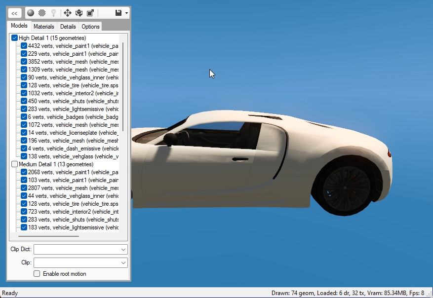
Upon importing, you will notice that the vehicle has only one wheel. This is because the game instances (re-uses) wheel_lf for all other wheels.
Wheel meshes do not have vertex groups but are instead rigged by a Child Of Constraint (as explained in Drawables > Rigging).
Also, wheel meshes have the Is Wheel Mesh property ticked under Object Properties > Sollumz.
That's all that's needed for setting up wheel meshes!
In Sollumz Tools > Fragment > Create Fragment Objects is a tool called Generate Wheel Instances. This tool will create instances of the wheel, allowing you to better preview what it looks like in-game. This is useful when positioning the wheel bones.
Drawables are objects that hold mesh data, skeleton data, and shader data. It can be thought of as the game engine's mesh format. YDR files contain one Drawable and are typically used for static mapping but are also used for dynamic props in some cases. In cases where a prop consists of multiple breakable parts, Fragment (.yft) objects are used instead.
Drawable
ShaderGroup
Shaders
TextureDictionary
Skeleton (sometimes)
DrawableModelsHigh
Geometries...
DrawableModelsMed
Geometries...
DrawableModelsLow
Geometries...
DrawableModelsVeryLow
Geometries...
Lights (sometimes)Drawables consist of multiple "Drawable Models" which hold the actual mesh data. Drawable Models are organized into High, Medium, Low, and Very Low detail levels. In every Drawable there is also a list of the shaders used and the parameters for each shader. Sometimes there are textures embedded in the file as well. Drawables can also contain skeleton data, but it is not required. This is usually only found in dynamic Drawables (objects affected by physics) such as props or in Drawables that are animated. Lastly, Drawables can contain lights, where each light contains light properties such as direction, falloff, color, etc.
In Blender, the hierarchy for Drawables consists of one parent Drawable object (either an empty or an armature depending on whether or not the Drawable has skeleton data) and Drawable Models (mesh objects).
Now we are at the last step of the interior tutorial the only thing we need is to place the interior into the world.
Start by opening the folder where all your files are located so the files wil be loaded into the game. Open the navbar and press open folder.
When you have opened the folder everything should be in the project manager, and it is now time to add the ymap. Go add the ymap and a new entity and replace prop_alien_egg_01 with the name of the interior as defined in the ytyp in this tutorial I called it tutorial_interior_col.
Now it is time to place it the right place, and it is now that the mirror we created earlier come in handy. Select the model in blender and open General > Object Location & Rotation Tools and press the most left button to copy the coordinates to clipboard the go into CodeWalker and paste the coordinates into the project manager.
Now it's time to calculate the flags and extents by selecting the ymap and press the calculate buttons and here you can also name the ymap what you want to call it in the name field then save the ymap.
We are almost done we are just missing the manifest file which we can auto generate by pressing Tools and the generate manifest and then save.
Now we are ready to load everything into the game.
Vehicle windows are defined in the physics properties of the window collision. See window_lf.col in adder.yft for example.
Enabling Is Glass Window will cause the window properties to appear. The only property you should have to change here is the Window Material. This is the material that the corresponding window mesh uses. Looking at the window_lf mesh materials, we see that it uses two vehicle_generic_glasswindows2 materials.
This is because one material represents the inner glass and the other represents the outer glass. Go into Edit Mode and select the vertices of each material to see which one represents the outer glass. In this case, it's the material without the ".001" so that's the one that the glass window should reference.
That's all that is needed for working vehicle windows!
You will notice that all vanilla vehicles have "shattermaps", which is an image that defines the border of the glass-breaking pattern. These aren't 100% necessary for working vehicle windows but will result in better-looking glass shatter patterns.
In Sollumz, shattermaps are represented as planes with a single texture. For example, adder.yft has an object called windscreen_shattermap which is parented to windscreen.col.
These are always low-res bitmap greyscale textures. Currently, Sollumz has no tools for creating shattermaps, so your best bet is to copy shattermaps from vanilla files and work off of those.
Collisions are well, collisions. whether that is for players, bullets, vehicles etc. There is 3 main types of .ybns, the normal version(s), hi@ versions which is for weapon bullets, and ma@ collisions that are used to procedurally spawn grass and other things like garbage on the street.
BoundComposite
BoundGeometryBVH
BoundPolyMesh
BoundBox
BoundPolyBoxThe Bound Composite is the top most part of the hierarchy, it doesnt control much on its own. The Bound GeometryBVH controls things like which things collide with the Bound Poly Mesh / Boxes. You can disable or enable certain flags here t o disable collision for specific object types. The Bound Poly Mesh / Box is the collision model itself, what you are actually colliding with. It is here where you can add or remove Collision materials and apply flags to said materials to control the physics of the collisions further. Also, the "Procedural ID" setting is used mainly for ma@ collision ybns to spawn procedural objects like trash on the ground. The "Room ID" Setting is used for setting up different rooms for MLOs.
For your textures and materials to work correctly inside of GTA V, you will need to use 'Sollumz Shaders'. these are simply materials that are set up correctly for use with GTA V assets.
To get started, within the Sollumz Tools found in the Toolbar, navigate to Drawables -> Shader Tools
Here you can find a list of all usable shaders within GTA V. you will quickly notice just how many shaders there are, and you might be intimidated by the amount, but around 80-90% of these shaders are not used frequently or at all for props.
Next, we will need to decide which shader is right for our asset. some key things to keep in mind when deciding which shader to use are:
There are two import settings that determine how Fragments import: Split By Group and Import with _hi.
Split By Group will split the Drawable by vertex group. This is typically what you want when editing vehicles, as vehicles are skinned (i.e. rigged with weighted vertex groups), so there is typically only one Drawable Model containing many vertex groups as opposed to multiple Drawable Models each linked to a bone (see for more info on rigging Drawables).
The Drawable Dictionary is a container that holds a collection of drawables. Its primary use is for storing LOD models, ped components, ped props, mesh minimaps and instanced props.
It is recommended that you read the Drawable documentation page before creating a Drawable Dictionary, as it consists of drawables.
For the hierarchy, several drawables exist as regular game-ready assets, but all of them share one parent drawable dictionary object.
z_z_alien.yft
z_z_fred.yft
z_z_fred_large.yft
z_z_wilma.yft
z_z_wilma_large.yft
a_c_boar.yft
a_c_cat_01.yft
a_c_chickenhawk.yft
a_c_chimp.yft
a_c_cormorant.yft
a_c_cow.yft
a_c_coyote.yft
a_c_crow.yft
a_c_deer.yft
a_c_dolphin.yft
a_c_fish.yft
a_c_hen.yft
a_c_humpback.yft
a_c_killerwhale.yft
a_c_pig.yft
a_c_pigeon.yft
a_c_poodle.yft
a_c_pug.yft
a_c_rabbit_01.yft
a_c_rat.yft
a_c_rhesus.yft
a_c_seagull.yft
a_c_sharkhammer.yft
a_c_stingray.yft
a_c_westy.yft
a_c_whalegrey.yft
a_c_chop.yft
a_c_husky.yft
a_c_mtlion.yft
a_c_retriever.yft
a_c_rottweiler.yft
a_c_sharktiger.yft
a_c_shepherd.yft
a_c_chimp_02.yft
a_c_rabbit_02.yft
a_c_panther.yft
a_c_chickenhawk.yft
a_c_rhesus.yft
a_c_seagull.yft
a_c_chop_02.yft
a_c_chickenhawk.yft Fragment
Drawable
DrawableDamaged (sometimes)
Physics
Composite
CompositeDamaged (sometimes)
PhysicsGroups
PhysicsChildren
VehicleGlassWindows
GlassWindows (currently not supported)
Lights.ybn.xml
🟩
🟩
Fragment
.yft.xml
🟧
🟧
Clip Dictionary
.ycd.xml
🟧
🟧
Map Data
.ymap.xml
🟩
🟩
Archetype Definition
.ytyp.xml
🟩
🟩
Props
🟩
Shader preview
🟧
Cloth yfts
🟩
Time Cycle
🟥
Lod Lights
🟥
Entity Extensions
🟩
Entity Sets
🟩


Does my asset utilize a normal map?
Does my asset utilize a specular map?
Do my textures contain an alpha channel?
for this example, the asset uses a normal and specular map, but no alpha. so for this shader we will use "normal spec".
So now that we have decided which shader we will be using, we can now go ahead and create the shader. To do so, you can either press CTRL + F within the shader list and search for "normal_spec", or you can scroll manually.
Once you have located the shader, select it by clicking it. it should now be highlighted. next, select your prop model, and click the "Create Shader Material" button.
If you now navigate to the Material tab on the bottom right panel with your prop model selected, you will see your newly created shader.
another thing you will notice is the "Sollumz" tab within the Material tab. Within this Sollumz tab is where you will be controlling everything related to this specific shader.
If you expand the Texture Parameters panel, you will see the 3 different texture slots:
DiffuseSampler (Diffuse / Colour map)
BumpSampler (Normal / Bump map)
SpecSampler (Specular Map)
you can go ahead and click the folder icon on the right to open up the file explorer window and select the corresponding textures for each.
Once you apply each texture, ensure the BumpSampler Color Space is set to "non-Color" otherwise it will look incorrect within blender, but will be fine when you export.

Switch to Face Select.
Select all faces by pressing A or using the CTRL+A shortcut.
Go to Vertex Groups, click Assign button and exit Edit Mode.
Now all of the selected faces are properly set to the bonnet vertex group.
Our new custom bonnet model has to be considered by Sollumz as a valid part, so we have to move the mesh by expanding Adder's armature then drag and drop bonnet's Drawable Model inside adder.mesh
A replacement custom part has also to be linked to the armature, you can do this via Armature modifier.
Go to Modifiers tab.
Add an Armature modifier.
Select your vehicle's armature.

adder.yftNotice how each object represents a separable part of the vehicle. Since it's split by vertex group, each object will only have one vertex group.
Each object also has an armature modifier with the Fragment as the target object.
Vehicle Fragments have an additional LOD level that is stored in a separate file named <fragment name>_hi.yft. For adder, it would be called adder_hi.yft. This is the highest level of detail and is what the player sees when close to the vehicle (i.e. when driving). It is very cumbersome to work on two separate YFTs so Sollumz stores this extra LOD level in the Very High LOD level. This enables you to work on both YFTs at once.
To import Very High LODs, first enable the Import with _hi option in the import settings panel, and ensure the _hi YFT is in the same directory as the non-hi YFT. Then, select the non-hi YFT and import.

In Blender, Drawable Dictionaries comprises a parent object and one or more drawable objects in its hierarchy.
Some features of Drawable objects cannot be inherited by Drawable Dictionaries. For example, the embedded collision cannot function when the drawable is in a drawable dictionary.
Furthermore, CodeWalker cannot identify the real name of a drawable in drawable dictionaries unless a nametable with resolved names is loaded. Thus, it is recommended to create a nametable whenever utilizing a drawable dictionary in your project to facilitate your own and others' modding processes.
When creating the archetype definition for a drawable in a drawable dictionary, it is necessary to fill the correct name of your drawable dictionary in the "Drawable Dictionary" blank to ensure it workds within the game.
For instance, if we have the drawable dictionary my_ydd and the drawable my_ydr in the scene. Then you should fill in "Drawable Dictionary" in the archetype as shown in the picture below:


The example prop used in this article is prop_container_05a.yft
You'll also notice that each Drawable Model is rigged using a Child Of constraint instead of vertex groups.
This is the case for all props. Typically each Drawable Model for a prop corresponds to a particular separable part of the Fragment. Notice there is a Drawable Model for the latch, each door, and the container itself.
This matches up with the bone hierarchy.
Each bone is parented to Prop_Container_05a and is thus affected by that bone. Every skeleton in the game engine always has one root bone that all the other bones are parented to.
If you attempt to add multiple top-level bones (bones with no parent) you will run into issues. Make sure there is a single "root" bone that all other bones are parented to!
Notice, too, that each bone has Use Physics enabled. This means that each of those parts will have physics in-game and will separate from each other.
As mentioned before, each bone with physics enabled must have an associated collision. However, there can be multiple collisions for a single bone. Notice for this prop, there is a single collision for the latch and the doors, but the container itself is comprised of 5 box collisions.
Each of these collision objects is linked to a bone via a Child Of Constraint.
Each collision also has its mass set in the Object Properties > Sollumz > Physics panel.
The LODs for each Drawable Model can be edited in the Mesh Properties > Sollumz LODs panel. As mentioned before, there are 4 LOD levels: High, Medium, Low, and Very Low. You will also see the "Very High" LOD level, but that is only used for YFT vehicles (see Fragments > Vehicle Setup).
For each LOD level, you can select the mesh it will use. You can also select any LOD level from the list and it will swap out the mesh that the Drawable Model uses.
LODs can also be changed for the entire hierarchy at once in the Sollumz Tools > General > View panel.
Alternatively, press Shift + V to open a pie menu for quickly viewing different LOD levels.
Sollumz provides a basic LOD generation tool that uses the decimate modifier.
Select the Drawable Model and Navigate to Sollumz Tools > Drawable > LOD Tools.
From here you can select which LOD levels will get created. Normally you'd model the highest LOD first, convert to a Drawable Model, then use that high LOD mesh as the reference mesh. The reference mesh is not affected in this process. Each subsequent LOD level is decimated by Decimate Step.
Your results will vary depending on the mesh, as the decimate modifier does not work well for all topologies.
You can also take advantage of Blender's instancing functionality and separate the LOD meshes into separate objects. This allows you to work on multiple LOD meshes at once.
Select the Drawable Model and Navigate to Sollumz Tools > Drawable > LOD Tools.
From here you can select which LODs to extract as well as what to parent the new objects to. You can either parent the objects to a collection or an empty object.
Notice how these new objects are using the same meshes as the ones defined in the Sollumz LODs panel.
Now, if you edit one of these object instances, the Drawable Model will be affected too.
Map Data such as object locations, car generators, occlusions, and lod lights are stored in the .ymap file format.
Basic Blender skills
Basic CodeWalker skills
A Drawable positioned at the world location you want it to be at
Open The 'N' Toolbar and navigate to Sollumz Tools -> Map Data
Then Click 'Create YMAP'
we can go ahead and rename our new ymap object, but ensure you rename it here as well.
Now, depending on what you will be using in this YMAP, we can return to the Map Data tab, and create the necessary groups.
with the ymap selected, click 'Entities'.
Next, parent your drawable positioned at the world position to the new 'Entities' object. (Shift + Drag)
Next, we can now export our YMAP. Select the YMAP object, and by either pressing V to open the Sollumz Pie Menu, or navigating to Sollumz Tools -> General -> 'Export CodeWalker XML', Export your YMAP Object.
There is a handful of export options related to ymap in the export window, keep these in mind in case you are running into any issues.
Lastly, convert the .XML file back to the binary .YMAP by dragging the .XML into any RPF archive in CodeWalker RPF Explorer. It's Recommended you create a new RPF archive in your GTA 5 Root Directory.
All light types have a Flashiness parameter, here you can set a value to make the light flicker or flash in a specific predefined way.
The default value is set to 0, or constantly visible.
Archetype definitions (.ytyp) is basically the configuration file to define properties of objects. inside the .ytyp you will find multiple Archetypes, each archetype is for one object, there is 3 types of archetypes, Base, Time and MLO. Base is for .ydr, .ydd, .yft objects, Time archetypes are for time based objects such as window emissives that only show up at night. MLO archetypes are for MLOs (.ybn) objects.
Drawable Dictionary
Drawable#1
ShaderGroup
Skeleton (sometimes, mostly seen on ped components)
DrawableModelsHigh
DrawableModelsMed
…
Drawable#2
Drawable#3
Drawable#4
Drawable#5
…


Once Per Second (3)
Light flashes 1 time per second
Twice Per Second (4)
Light flashes 2 times per second
Five Per Second (5)
Light flashes 5 times per second
Random Flashiness (6)
Truely random flashiness
Off (7)
Unused (8)
An unused value, has no effect
Alarm (9)
Flashes like an alarm, possibly tied to audio alarms?
On When Raining (10)
Flashing begins when weather is set to rain
Cycle 1 (11)
A predefined flashing cycle
Cycle 2 (12)
A predefined flashing cycle
Cycle 3 (13)
A predefined flashing cycle
Disco (14)
Flashes like a disco ball
Candle (15)
More so a flicker, like a candle
Plane (16)
Likely used for plane lights, the navigation ones
Fire (17)
Similar to the candle, but flickers faster
Threshold (18)
Electric (19)
Flashes like an electric ceiling light
Strobe (20)
Flickers like a strobe light, very fast and intense
Constant (0)
Light shines constantly, no flashing
Random (1)
Takes the lights Extent value as a factor for the random value
Random Override If Wet (2)


Archetype type (Base, Time, MLO)
Name
Archetype Name
Special Attribute
0-13 (mainly used for doors)
Texture Dictionary
Texture dictionary (.ytd)
Clip Dictionary
Linked YCD Animation (.YCD)
Drawable Dictionary
Physics Dictionary
Blank or same as Archetype Name if embedded
HD Texture Distance
Distance at what the HD Textures (+hi.ytd, +hidr.ytd) load
LOD Distance
Distance at which the object unloads
Asset Type
Assetless, Drawable Dictionary (.YDD), Drawable (.YDR), Fragment (.YFT), Unintialized
Asset Name
Same as Archetype Name
Linked Object
Object in blender scene linked to the archetype

Type
OpenRPF for Enhanced https://www.gta5-mods.com/tools/openrpf-openiv-asi-for-gta-v-enhanced
Prepare the folder with your Legacy assets
Create a folder for Enhanced assets (in this example - gen9)
Open up CodeWalker RPF Explorer, and head to Asset Converter
Select a folder with Legacy files
Select a folder to save converted files
Untick Include subfolders and click Process
And it's done! Conversion process was completed and your mod is ready to be used in Enhanced.
In order to use modified files in the Enhanced version, an OpenRPF file loader is needed. Installation process is very simple.
Download OpenRPF from the link on the top of this tutorial.
Extract ZIP archive.
Select dsound.dll and OpenRPF.asi and drag&drop them to GTAV Enhanced installation folder
There is no rose without thorns, especially in game modding. Some unexpected behaviours can occur when porting content to Enhanced.
Q: My car is spawned, when I'm entering the car, I got ERR_GFX_STATE crash.
A: The issue is in the texture inside .ytd file. A texture starting with script_rt_ name is saved in incorrect format. For such file, only D3DFMT_A8R8G8B8 is expected by game.
To fix this issue:
Extract texture to .dds
Open texture in image editor supporting editing .dds files (i.e. GIMP)
Save the texture using RGBA8 texture format, without mipmaps.
Replace texture by the saved one from moments ago and save file.
Close and open adder.ytd file.
Go to Details tab, find G9_Flags column and change the value to 2490920, if CW didn't set it by default.
Q: Game crashed even when I didn't enter the car. A: Check the material/geometries amount of the converted vehicle. GTAV Enhanced has a limit of 128 materials/geometries per file and exceeding that value leads to crashes.
A plausible workaround for that issue is to export _hi.yft and .yft files to .XML, import them using Sollumz, export to .XML and import these files by CW RPF Explorer. 1. Select files in CW RPF Explorer, click right mouse button and select Export XML button.
Import XML file in Blender using Sollumz
Select the root component from the Layers menu and Export CodeWalker XML
In CW RPF Explorer, click right mouse button and select Import XML button and select both exported from Blender.
If this process didn't reduce material/geometries amount, then vehicle mod isn't well optimized for games and ask mod author about fixing it for GTAV Enhanced.


Interior Only
Light only renders inside interiors
Exterior Only
Light only renders outside of interiors
Dont Use In Cutscene
Vehicle
Archetype flags are used to define certain properties of the archetype, like its vertex colours and its physics and how it renders
Unknown 1
Unknown 2
Unknown 3
Ignore Artificial Lights State
Texture Projection
Enables Texture Projection
Cast Shadows
Casts Shadows
Cast Static Shadows
Cast Static shadows from the light (Static ydr meshes)
Cast Dynamic Shadows
Cast dynamic shadows from the light (player shadows)
Calculate From Sun
Calculate light intensity by time of day and sun brightness
Enable Buzzing
Enables electric light buzzing sound
Force Buzzing
forces electric light buzzing sound
No Specular
Disables light from showing up in specular reflections
Both Interior and Exterior
Interior lights bleed out of the MLO and vise versa
Corona Only
Only renders the corona of the light
Not In Reflection
Do not render light in mirror reflections
Only In Reflections
Only Render light in mirror reflections
Enable Culling Plane
Enables the lights culling plane
Enable Volume Outer Color
Enable Volume outer Color of the light
Higher Res Shadows
Increase Shadow Resolution
Only Low Res Shadows
Use Low Resolution Shadows
Far Lod Light
Force Light to be far LOD Light
Dont Light Alpha
Dont effect the alpha of objects
Cast Shadows If Possible
Cutscene
Moving Light Source
Use Vehicle Twin
Force Medium LOD Light
Corona Only LOD Light
Delay Render
Disables the light
Already Tested For Occlusion

Unknown 4
Unknown 5
Static
Freeze entity, disables physics
Unknown 7
Instance
Used for procedural objects
Unknown 9
Bone Anims (YCD)
Enable Bone Animations
UV Anims (YCD
Enable UV Animations
Invisible but blocks lights/shadows
Unknown 13
Object Won't Cast Shadow
Disable shadows for object
Dynamic
Enable Physics
Unknown 19
Unknown 20
Unknown 21
Unknown 22
Unknown 23
Unknown 24
Unknown 25
Unknown 26
Enable Special Attribute
Unknown 28
Disable Red Vertex Colour Channel
Disable Red Vertex Colours
Disable Green Vertex Colour Channel
Disable Green Vertex Colours (used alot for props)
Disable Blue Vertex Colour Channel
Disable Blue Vertex Colours
Disable Alpha Vertex Colour Channel
Disable Alpha Vertex Colours

Used to add things like particles, ped spawns, ladders, and light shafts to be attached to the entity
Used for:
Used For: Attaching / Spreading procedural objects
Used for:
Used For: Spawning / overriding ped spawns
Used For: Attaching peds / ped scenarios to objects
Used For: Light Rays / God Rays
Often the easiest way to get into ped editing is to start simple: Let's edit an existing model from GTA for a freemode ped, so we can learn the basics.
One thing you should know is that there are generally two different types of peds for GTA: "streamed" and "non-streamed". For a basic explanation, just know that peds use YDD (drawable dictionary) files for their models instead of YDR. For streamed peds, all of their 'parts' (ie shirt, shoes, head, etc) are separate YDDs. For non-streamed peds, all of those parts are put together into 1 single YDD. Streamed peds are generally easier for beginners to start with editing, because you can edit and export 1 piece at a time so if you mess up, you know it's just that 1 part that isn't working.
MP Freemode both male and female are both "streamed peds". This means that all of their parts are separate. If you wanted to see a 'base body' in blender to work with, you'll need to import several different YDDs: a HEAD, an UPPER, a LOWR, and a FEET.
Highest possible scale value
Min Scale Z
Lowest possible scale value on the Z axis
Max Scale Z
Highest possible scale value on the Z axis
Min Z Offset
lowest possible offset on the Z Axis
Max Z Offset
Highest possible offset on the Z Axis
Object Hash
procedural object to use
Flags
Offset Position XYZ
Extension offset relative to entity origin
Offset Position XYZ
Extension offset relative to entity origin
Ped Model Set
Radius
Radius of the Spawn Point Override
Time Till ped Leaves
Time until ped stops task (in minutes?)
Available in MP/SP
Whether it is SP only or MP
Scenario Flags
Offset Position XYZ
Extension offset relative to entity origin
Interior Name (if inside one)
Required Map
Probability
Chance for the scenario to spawn
Time Till Ped Leaves
Time until ped stops task (in minutes?)
Radius
Radius of the Spawn Point
Start
Time the scenario starts
End
Time the scenario ends
High Priority
Prioritizes spawning of scenario
Extended Range
Extend range at which the scenario can spawn relative to the player
Short Range
Decrease range at which the scenario can spawn relative to the player
Available in MP/SP
Whether it is SP only or MP
Scenario Flags
Offset Position XYZ
Extension offset relative to entity origin
Color of the Light Shaft
Intensity
Intensity of the Light Shaft
Flashiness
Flags for how fast and if the Light Shaft should flash / flicker
Flags
Only Possible flags are 35, 99, 83, 115, 51
Fade In Time Start
When the Light Shaft should begin to appear
Fade in time End
when the Light Shaft is fully visible
Fade Out Time Start
When the Light Shaft should begin fading away
Fade Out Time End
when the Light Shaft Shouldnt be visible
Fade Distance Start
Distance at which the Light Shaft begins Fading
Fade Distance End
Distance at which the Light Shaft is fully Faded
Softness
Corner A XYZ
Top Left Corner Coords
Corner B XYZ
Top Right Corner Coords
Corner C XYZ
Bottom Right Corner Coords
Corner D XYZ
Bottom Left Corner Coords
Offset Position XYZ
Extension offset relative to entity origin
Name
Expression Dictionary Name
Expression Name
Creature Metadata Name
Initialize on Collision
Offset Position XYZ
Extension offset relative to entity origin
Name
Extension Name
Radius Inner
Inside radius of a circle around the extension
Radius Outer
outside radius of a circle around the extension
Spacing
Distance between procedural objects
Min Scale
Lowest possible scale value
Name
Extension Name
Offset Rotation XYZ
Extension rotation
Disturbance Type
Bone Tag
Linked bone's Bone Tag(Optional?)
Size XYZW
Name
Extension Name
Scenario Type
Scenario type from .ymt scenarios
iTime Start Override
When the override should start
iTime End Override
When the override should end
Group
Ped Group
Name
Extension Name
Offset Rotation XYZ
Extension rotation
Spawn Type
Ped Type
Group
Ped Group
Density Type
How dense the light shaft should be
Volume Type
Shape of the shaft
Scale By Sun Intensity
Use in game sun intensity to effect brightness
Direction Amount
Length
Length of the Light Shaft


Max Scale
Flags
Model Set
Interior
Color
One other note before we start: All peds, whether streamed or non-streamed, have a SEPARATE FILE called a YFT for their skeleton. For whatever ped you are editing with Sollumz, you will need their YFT file so that Sollumz knows what their bones are.
Let's start getting ready to get into Blender! The first step is to export the male and female Freemode ped skeletons (YFTs) to use when importing and exporting components that are rigged to the ped. These are located at x64v.rpf\models\cdimages\streamedpeds_mp.rpf and can be saved separately to be used with any freemode ped clothing or accessories you edit in the future.
If you haven't already created a folder somewhere on your computer to work on this project, do that now. Then, right-click the mp_m_freemode_01.yft and press Export XML.... Make sure you're keeping track of where you exported the XML to. It will need to be in the same folder as the YDD when we import into Sollumz.
Now we'll export the model we actually want to edit, as well as a texture for it. If you didn't already know of it, tobii.space is a good visual reference for most of the freemode components. It has most DLC clothing, although it is missing some of the newer updates. Today we already know what clothing piece we're using, so let's head back over to Codewalker RPF and grab the file.
Open up CW RPF and type mp_m_freemode into the searchbar
If you click "Name" at the top to sort by name, you'll then see a list of all of the MP Male folders. You'll notice there are multiple folders for every DLC. This is the original DLC folder, and then patchday folders that hotfixed any issues R* had with various pieces of clothing.
The 🟥 outline is all of the base MP male DLC folders
The 🟧 outline highlights all of the DLC names. Notice the original DLC and all of the patchday hotfixes.
The 🟩 outlines the original base game DLC folder.
Right now we aren't going to worry about any hotfixed files, so just click into the original DLC folder. If you are ever editing GTA assets, though, you should always look through the patchday folders for whatever component you're trying to edit so that you can work off of the most up-to-date version.
Now that we're inside the base folder, you'll see a long list of all the base game components and their YTD textures. Make sure you're sorted by 'Name' so that everything is alphabetical, and then scroll down until you see the JBIBs.
For the purposes of our tutorial, let's export jbib_007_u.
Right-click on jbib_007_u.ydd
Select export XML...
Export location: Make sure you export to the same folder you exported the YFT earlier.
Now let's quickly visit the folder you've just exported the file to. In the folder, you should have a couple of things. Firstly the mp_m_freemode_01.yft.xml, then .ydd.xml of our jbib & there should also be a folder named jbib_007_u.
Whenever you are exporting a model that has embedded textures, Codewalker RPF will create a folder named after the model you exported to XML with all of the embedded textures placed inside of it.
Go ahead and click into the folder and take a peek at the embedded textures! You should see two: a normal texture and a specular texture. To quickly explain these: A normal helps emphasize clothing details like wrinkles & a specular helps display the glossiness or matte of your clothing.
Most freemode clothing components have an embedded specular texture and normal texture. When you go to make your own models later on, you'll need to learn how to create these yourself. For now, they have already been made for us. So get familiar with them while you can!
You might have already noticed, but there's one texture we don't have yet: A diffuse texture. The diffuse texture for clothing YDDs stays un-embedded from the model and in a separate file called a YTD (texture dictionary), and you can have up to 26 of them (A to Z) for any single YDD. We don't need the texture for our editing today, but it's nice to have a visual reference, so let's grab one now.
In Codewalker RPF right below where you found the YDD we exported, should be the YTD files. Scroll down until you see jbib_diff_007_a_uni.ytd and export it to XML. It will create a sub-folder named jbib_diff_007_a_uni with the texture inside of it.
Do a final check before opening blender. Your folder should look like this:
Your .yft.xml is in the same folder on the same level as the .ydd.xml . That's the import part!
If you would like, you can copy/paste the diffuse texture from the jbib_diff_007_a_uni to the "embedded textures" folder jbib_007_u . This will allow Sollumz/Blender to automatically find the texture when you go to import. Otherwise, you can link it manually later on.
With Blender open:
click File
Import ► Codewalker XML
Navigate to the folder you exported the XMLs
Click jbib_007_u.ydd.xml and from the side-menu options make sure you select 'Import External Skeleton'
You should now be looking at something like this:
Let's make sure we imported correctly. In scene collection:
Expand jbib_007_u and then jbib_007_u.001 and click on SKEL_ROOT
In the properties window, click on the Object Data Properties tab
Expand Vertex Groups (if its not already) and make sure they are all named.
If you see named bones like SKEL_L_Hand etc then you're good to go! If you see something like UNK.001 you did not follow the correct steps for exporting the YFT portion of this tutorial. Go back up, re-read, and try again.
With everything imported properly, let's get ready to actually edit! First things first, we probably want to change our viewport to actually see what we're working with.
Personally, I like to change the 'color' to Texture and 'lighting' to MatCap, but you can play around in this menu and see what works for you.
Once we have that set, your shirt might look like this:
If you left the diffuse texture in it's own jbib_diff_007_a_uni sub-folder, you'll see our jacket is pink. That's fine! We can just link up our diffuse texture now.
Top-left, go to File ► External Data ► Find Missing Files
Navigate to your project folder and select the jbib_diff_007_a_uni sub-folder where you will see the jbib_diff_007_a_uni.dds. Then press 'find missing files'.
It's good to know this method, as you will use it in other parts of Sollumz modding as well for things like props and MLOs. You might see a yellow warning popup at the bottom of your blender that says it cannot find 'givemechecker.dds' . This is fine to ignore.
Head back to the 3D viewport (instead of shader editor) and we can see our jacket now has the diffuse texture:
Great! Just one more thing to do before we actually edit. When importing into blender our vertices have unmerged and we've lost our sharp edges. We want all of that back so that we can have the most accurate view of what we're working with and what it will look like in-game.
To fix things, let's do the following:
Select SKEL_ROOT in scene collection
In 3D Viewport, Tab into Edit Mode
Select everything (Default: A key)
Merge ► By Distance (Default: M key)
In the bottom left for the 'Merge by Distance' window, expand it and tick on Sharp Edges
Clothing has 3 LODs (level of detail): high, medium, and low. We also need to do the same thing for our medium and low LODs.
The easiest way to switch between LODs quickly is to press SHIFT + V (make sure you are no longer in edit mode) to bring up the Sollumz Object Visibility wheel.
The three options on the right-side of the wheel are the ones you'll be using for clothing YDDs. Switch to Medium, repeat the same steps above. Then switch to Low, and do it once more.
We're ready to edit! Switch back to High LOD with SHIFT + V and tab into edit mode. You can make any changes you want here. I'll delete the sleeves for the purpose of this tutorial.
Now that I've removed the sleeves, I have 2 things to resolve:
I need to fill in the holes where the sleeves used to be
I need to create new sharp edges to tidy up the model
The reason we want to fill in the holes is because GTA uses back-face culling. What this means is that the faces on the model do not have both a viewable "front" and "back". Instead, the front-facing side is visible and the back is invisible. We can see this in action in blender by going back up to the viewport shading options and turning it on.
You can see the "back side" of the model is invisible now. We need to fill in those holes. There are two ways to fix this.
First, go back into edit mode and select all of the vertices around the edge.
Then you have two options. You can either press F to fill in the hole, or you can extrude the hole and then merge the vertices from the extrusion. For this tutorial, I'll be doing the second method.
Select the vertices around the edge
Extrude (default E key)
With your mouse, move the new points slightly inward
Scale the vertices together (default S key) then merge them (M Key) ► at center
You might notice that our new geometry looks a little weird. Almost as if its shiny in places.
What's happening here is we have bad normals. To be clear, there is a difference between the embedded "normal texture" (sometimes also called a bump map) and geometry normals. If you'd like to learn more about normals, there are plenty of youtube videos that can help.
For now I'm just going to reset them to clear up this issue! With my geometry selected go to Mesh ► Normals ► Reset Vectors
Once that's done, everything should be looking much betterr.
Since this is the edge of the shirt, I'd also like to set some sharp edges along the same loop we just filled in. Sharp edges add a more "crisp" line in geometry that is clearly visible in-game. When you use them properly, they can add a little extra emphasis to your model quality. There's no rule of when or when not to use sharp edges, it's up to you to follow the lines of clothing and determine where they would make sense.
For now I'll go to edge select & select the loop I filled in, then right-click and press "mark sharp"
Now do the same thing with the other side.
With that done comes the boring part: Repeating the same process with the medium and low LODs! With custom models, you would have all of this already finished before you create your LODs but when editing existing clothing, you need to either edit everything the same or create new LODs after you've edited.
For this tutorial, you should delete the sleeves on the med/low LODs so that they look visually similar, but it's up to you whether you want to fill in the sleeve holes like we did here for High LOD. Chances are that from a distance people won't be able to see that small detail anyway.
With all of the LODs edited, we're now ready to export!
In the outliner window, right-click jbib_007_u and select hierarchy
Then go top-left to File ► Export ► Codewalker XML
It's best to create an 'export' folder so that you are not overwriting the original. That way if you mess up, you don't have to go grab the ydd xml all over again.
navigate into Export folder
Export
The window will close and at the bottom of your blender you should see a message like "exported in 0.12 seconds".
Now in our export folder, we should have our new .ydd.xml and a copy of the embedded textures folder with our normal/specular textures inside.
You can now head back over to Codewalker RPF and import the XML to turn it back into a YDD & preview it!
Our model is finished! Now you can replace the existing one or create an addon with the same textures and test in-game. In-game you might see it clips with the underarms as you move around. That's due to something called "weight painting". More about that to come in future tutorials!
99% of the time you want Color 1 to be #FF8000 and Color 2 to be #000 with 0 alpha.
Color 1 setup:
Color 2 setup:
Make sure both are set to "face corner" and "byte color":
Answer: This has to do with Vertex Colors. Color 1 determines the lighting a ped object should take on, and Color 2 is to deal with sweat or wind effects. Your clothes are shaking due to wind. To turn off wind effects, make sure Color 2 is black #000 (see above).
Answer: This has to do with Vertex Colors. Color 1 determines the lighting a ped object should take on. Most MP clothing uses hex color #FF8000 for Color 1 (#000 with no alpha for Color 2, see above)
Answer: This has to do with Vertex Colors. Color 1 determines the lighting a ped object should take on, and Color 2 is to deal with sweat or wind effects. Your clothes are shiny in the sun due to sweat. To turn off sweat effects, make sure Color 2 has no alpha:
Answer: For MP Freemode YDDs using PED material (or streamed ped YDDs) it is required to embed both a normal and specular texture(s). If you see your texture but with a checkered overlay, most likely you are missing one or both.
Answer: Most of the time this is due to clothing not being rigged. Either you did not import with external skel (see Importing the Files) or your import was okay but you didn't actually rig your mesh (empty vertex groups).
Answer: Several things could be wrong. Either you:
Did not name your embedded textures correctly (should follow R* format so component_normal/spec_number for example: jbib_normal_000 and jbib_spec_000)
The alpha RGB channel on your specular texture (viewable in programs like photoshop) is not setup correctly
You moved the UVs for the skin (you should not do this)
Your diffuse is not square or not Power-of-2 (256x256 or 512x512 etc). _r clothing should be square to follow original MP skin dimensions.
This is an intermediate problem that has many possible issues. For a more in-depth explanation of these problems (and a walk-through of the solutions) please watch this video:
For ped emissive to work correctly on clothing, set Color 1 to #FFBAFF. Keep Color 2 #000/no alpha to disable sweat/wind.


In this page you can find all vehicle shaders used on vehicles and their technical usage
vehicle_paint1
Typical vehicle paint shader, used on most vehicles in GTA V.
vehicle_paint1_enveff
Basic vehicle paint shader with additional feature of applying snow.
Vertex Alpha: visibility of snow samplers (black - non applied, white - applied)
vehicle_paint2
A very similar shader to vehicle_paint1, with dirt mapping moved to first UV map.
vehicle_paint2_enveff
A copy of vehicle_paint2 with additional feature of applying snow.
Vertex Alpha: visibility of snow samplers (black - non applied, white - applied)
vehicle_paint3
Used for liveries on a car.
vehicle_paint3_enveff
A copy of vehicle_paint3 with additional feature of applying snow.
Vertex Alpha: visibility of snow samplers (black - non applied, white - applied)
vehicle_paint3_lvr
Variant of vehicle_paint3 with tileable livery via second UV Map.
vehicle_paint4
Used for metal worn effect and/or livery on a car.
vehicle_paint4_emissive
Very same vehicle_paint4 shader with support of emissives.
vehicle_paint4_enveff
vehicle_paint4 shader, used for metal worn effect and liveries on a car.
Vertex Alpha: visibility of snow samplers (black - non applied, white - applied)
vehicle_paint5_enveff
Used for metal worn effect and liveries on a car.
Vertex Alpha: visibility of snow samplers (black - non applied, white - applied)
vehicle_paint6
Used for metal bolts on planes, applying liveries, metal worn effect.
vehicle_paint7
Used for metal worn effect and liveries on a car.
vehicle_paint7_enveff
Used for metal worn effect and liveries on a car.
Vertex Alpha: visibility of snow samplers (black - non applied, white - applied)
vehicle_paint8
Used for metal worn effect and liveries on a car.
Vertex Alpha: visibility of snow samplers (black - non applied, white - applied)
vehicle_paint9
Used for metal worn effect and liveries on a car.
Vertex Alpha: visibility of snow samplers (black - non applied, white - applied)
vehicle_lightsmeissive
Allows the light to be lit.
Lights ID values for different type of vehicle lights, available in Fragments / Vehicle Light IDs
vehicle_vehglass
Shader specifically tailored to work with windows and other glasses.
vehicle_vehglass_inner
Identical shader to vehicle_vehglass, used for inner side of windows/glasses, with limited dirt intensity.
vehicle_interior
Simple interior shader with normal map support.
vehicle_interior2
Simple interior shader without normal map support.
Simple interior shader without normal map support.
vehicle_mesh
Extensively used for metallic vehicle parts, like exhausts, engines, chassis parts.
vehicle_mesh_enveff
Extensively used for metallic vehicle parts, like exhausts, engines, chassis parts with additional feature of applying snow.
Vertex Alpha: visibility of snow samplers (black - non applied, white - applied)
vehicle_tire
A shader for wheels, cannot be used on any other vehicle parts.
vehicle_tire_emissive
vehicle_tire shader with emissive support
vehicle_dash_emissive
Shader dedicated for emissive dials being lit up at night.
vehicle_dash_emissive_opaque
Shader dedicated for emissive dials being lit up at night for opaque textures.
vehicle_licenseplate
Shader responsible for rendering vehicle license plates with changeable text.
vehicle_badges
Shader for vehicle badges.
vehicle_decal
Shader created for adding additional decals, scratches on the vehicle.
vehicle_decal2
Derivated from vehicle_decal, with dirt support.
vehicle_detail2
Used to add a leather detail effect to seats and dashboards.
vehicle_shuts
Shader utilized for inner sides of engine bay, doors, bonnet and boot.
vehicle_track/vehicle_track2
Shader for UV animation, hardcoded usage, in modded vehicles works only on the left side.
UVMap 0
Diffuse / Specular
UVMap 1
Dirt
UVMap 0
Diffuse / Specular / Dirt
UVMap 0
Diffuse / Specular / Dirt
UVMap 0
Diffuse / Dirt
UVMap 1
Second diffuse / Specular
UVMap 0
Diffuse / Dirt / Enveff tileable UV (edited in envEffTexTileUV)
UVMap 1
Second diffuse / Specular
UVMap 0
Diffuse / Dirt
UVMap 1
Livery / Specular
UVMap 0
Dirt / Diffuse tileable UV (edited in DiffuseTexTileUV)
UVMap 1
Tileable specular (edited in specTexTileUV)
UVMap 0
Dirt / Diffuse tileable UV (edited in DiffuseTexTileUV)
UVMap 1
Tileable specular (edited in specTexTileUV)
UVMap 0
Dirt / Diffuse tileable UV (edited in DiffuseTexTileUV)
UVMap 1
Tileable specular (edited in specTexTileUV)
UVMap 0
Dirt / Diffuse tileable UV (edited in DiffuseTexTileUV)
UVMap 1
Livery
UVMap 0
Dirt / Diffuse tileable UV (edited in DiffuseTexTileUV)
UVMap 1
Livery
UVMap 0
Dirt / Specular / Diffuse tileable UV (edited in DiffuseTexTileUV)
UVMap 1
Livery
UVMap 0
Dirt / Diffuse tileable UV (edited in DiffuseTexTileUV)
UVMap 1
Livery
UVMap 0
Dirt normal map
UVMap 1
Diffuse tileable UV (edited in DiffuseTexTileUV) / Snow sampler tileable UV (edited in envEffTexTileUV)/ Livery / Specular
UVMap 2
Dirt
UVMap 0
Dirt normal map
UVMap 1
Livery
UVMap 2
Dirt / Diffuse tileable UV (edited in DiffuseTexTileUV) / Snow sampler tileable UV (edited in envEffTexTileUV) / Specular
UVMap 0
Diffuse / Specular
UVMap 1
Dirt
UVMap 0
Diffuse / Specular
UVMap 1
Dirt
UVMap 0
Diffuse / Specular
UVMap 1
Dirt
UVMap 0
Diffuse / Normal map / Specular
Diffuse / Specular
UVMap 0
Diffuse / Normal map / Specular
UVMap 1
Dirt
UVMap 0
Diffuse / Dirt / Normal map / Specular
UVMap 0
Diffuse / Dirt / Normal map / Specular
Diffuse / Specular
Diffuse / Specular
UVMap 0
Plate background, Place background bump, Font, Font bump
UVMap 1
Dirt
UVMap 0
Diffuse / Normal map / Specular
Diffuse / Specular
UVMap 0
Diffuse / Dirt / Specular
UVMap 0
Diffuse / Normal map / Specular
UVMap 1
Detail (tileable)
UVMap 0
Diffuse / Normal map / Specular
UVMap 0
Diffuse / Normal map / Specular
UVMap 1
Dirt
UVMap 0
Diffuse / Specular
UVMap 1
Dirt


UVMap 0
UVMap 0
UVMap 0
UVMap 0


