Only this pageAll pages
Powered by GitBook
1 of 52

2.4

Loading...

Loading...

Getting Started

Loading...

Loading...

Support

Loading...

Loading...

Loading...

Tutorials

Loading...

Loading...

Loading...

Loading...

Loading...

Loading...

Creating the Archetype (.ytyp)

TODO

Loading...

Loading...

Loading...

Loading...

Loading...

Loading...

Loading...

Loading...

Loading...

Documentation

Loading...

Loading...

Loading...

Loading...

Loading...

Loading...

Loading...

Loading...

Loading...

Loading...

Loading...

Loading...

Loading...

Loading...

Loading...

Loading...

Loading...

Loading...

Loading...

Loading...

Loading...

Loading...

Lighting (.ydr)

Lights are well, lights that are embedded into .ydr or .yft objects. there is many different settings for these lights which can make it very tricky and confusing to get right.

Loading...

Loading...

Welcome

Thank you for using Sollumz, the only GTA V modding suite for Blender!

Prerequisite Knowledge

  • A basic understanding of modding in GTA V including using CodeWalker.

Requirements

Reporting Bugs and Making Feature Requests

Our Community

A basic understanding of Blender and 3D modeling. ()

Blender 4.0 or later -

Latest version of CodeWalker found in #releases channel.

If you think you've found a bug or you wish to request a feature, please use the . Be sure you extensively troubleshoot the issue first to ensure a bug is actually present.

Join the and be a part of our growing community!

This is a great place to start
blender.org
Download
issue tracker on GitHub
discord

Features

🟩 Fully implemented

🟧 Partially implemented

🟥 Not implemented

Sollumz cannot import binary formats directly. You must convert them to XML first using CodeWalker!

Since this plugin was designed around CodeWalker's XML file formats, OpenIV is not explicitly supported. You may experience issues going from Sollumz > CodeWalker > OpenIV. It's highly recommended that you just use CodeWalker.

File Formats

Asset Type
File Extension
Import
Export

Drawable

.ydr.xml

🟩

🟩

Drawable Dictionary

.ydd.xml

🟩

🟩

Static Collision

.ybn.xml

🟩

🟩

Fragment

.yft.xml

🟧

🟧

Clip Dictionary

.ycd.xml

🟧

🟧

Map Data

.ymap.xml

🟩

🟩

Archetype Definition

.ytyp.xml

🟩

🟩

Specific Features

Drawable (.ydr)

Feature
Support

Mesh editing

🟩

Embedded collisions

🟩

Shader editing

🟩

Terrain shader painting

🟩

Tint shaders

🟩

Props

🟩

Shader preview

🟧

Drawable Dictionary (.ydd)

Feature
Support

Editing Drawable Dictionaries

🟩

Importing with external skeleton

🟩

Static Collision (.ybn)

Feature
Support

Collision editing

🟩

Fragment (.yft)

Feature
Support

Vehicles

🟩

Breakable props (i.e. street lights)

🟩

Breakable glass props

🟩

Explodable props (i.e. gas tanks)

🟥

Ped yfts

🟥

Cloth yfts

🟥

Unsupported Ped YFTs

The following is a list of unsupported ped YFTs. These YFTs contain unknown ragdoll physics data that is not handled by Sollumz. Currently, it is not possible to create completely custom player skeletons.

z_z_alien.yft 
z_z_fred.yft 
z_z_fred_large.yft 
z_z_wilma.yft 
z_z_wilma_large.yft 
a_c_boar.yft 
a_c_cat_01.yft 
a_c_chickenhawk.yft 
a_c_chimp.yft 
a_c_cormorant.yft 
a_c_cow.yft 
a_c_coyote.yft 
a_c_crow.yft 
a_c_deer.yft 
a_c_dolphin.yft 
a_c_fish.yft 
a_c_hen.yft 
a_c_humpback.yft 
a_c_killerwhale.yft 
a_c_pig.yft 
a_c_pigeon.yft 
a_c_poodle.yft 
a_c_pug.yft 
a_c_rabbit_01.yft 
a_c_rat.yft 
a_c_rhesus.yft 
a_c_seagull.yft 
a_c_sharkhammer.yft 
a_c_stingray.yft 
a_c_westy.yft 
a_c_whalegrey.yft 
a_c_chop.yft 
a_c_husky.yft 
a_c_mtlion.yft 
a_c_retriever.yft 
a_c_rottweiler.yft 
a_c_sharktiger.yft 
a_c_shepherd.yft 
a_c_chimp_02.yft 
a_c_rabbit_02.yft 
a_c_panther.yft 
a_c_chickenhawk.yft 
a_c_rhesus.yft 
a_c_seagull.yft 
a_c_chop_02.yft 
a_c_chickenhawk.yft 

Clip Dictionary (.ycd)

Feature
Support

Skeletal Animations

🟩

UV Animations

🟩

Camera Animations

🟩

Light Animations

🟧

Map Data (.ymap)

Feature
Support

Entities

🟩

Box Occluders

🟩

Car Generators

🟩

Model Occluders

🟩

Physics Dictionaries

🟥

Time Cycle

🟥

Lod Lights

🟥

Archetype Definition (.ytyp)

Feature
Support

Base Archetypes

🟩

Time Archetypes

🟩

MLO Archetypes

🟩

Create rooms from vertices

🟩

Create portals from vertices

🟩

Entity Extensions

🟩

Entity Sets

🟩

Installation

Open Blender, go to Edit > Preferences > Add-ons

Click Install... and select the downloaded zip file.

Now enable the add-on by checking the checkbox.

Restart Blender.

Creating Your First Asset

Jump right in and create your first game asset by following one of our tutorials! We recommended you start with these tutorials first, as the other tutorials build off knowledge from these tutorials.

It's also highly recommended that you check out the documentation section. There you will find detailed information about each file type and how it is represented in Blender.

Download .

Sollumz
Creating Static Meshes
Creating Static Collisions
Creating Props
Drawables (.ydr)
🌐
💥
🎸
🌐

FAQ

Frequently Asked Questions

How do I import files to Blender with Sollumz?


When I import a YDR/YFT/YDD the textures are not loaded

  • From the CodeWalker RPF Explorer, open the asset with the textures.

  • Click the save icon in the top right, then click "Save All Textures"

  • In Blender, press the V key, then click Find Missing Files and select the folder where you saved the textures.

  • Alternatively, export all textures into a folder with the same name as the file you are importing. For instance, if you wanted to import adder.yft with all of its textures, you would export all textures to a folder called adder in the same directory. Then, when you import into Sollumz, all textures will be automatically loaded from the adder folder.


My MLO shows up in CodeWalker but not in game.

  • Make sure you generate a "_manifest.ymf" file from the CodeWalker project window with your MLO, YMAP, and YTYP in it.


I'm getting an error when importing a file.

  • 9 out of 10 times it is due to having an outdated Sollumz version. Try updating.


I'm getting the message No Sollumz objects in the scene to export! or No Sollumz objects selected for export!

  • Check if the "Limit to Selected" export option is ticked. If so, only the selected objects will export.

  • Make sure all of your objects have their sollum type set, otherwise, they will not be recognized by the add-on.

  • As a last resort, you can select the parent object and use Sollumz Tools > General > Debug > Fix Hierarchy


I'm getting the error TypeError: create_uvsphere: keyword "diameter" is invalid for this operator.

  • Update your Sollumz.


I'm getting the error KeyError: 'bpy_prop_collection[key]: key "Image Texture" not found'

  • One of your materials has a missing node connection between Color node and an Image Texture, which is 100% needed in order to export the model.

  • Check shading tab to find more.


I'm getting the error KeyError: 'bpy_prop_collection[key]: key "Principled BSDF" not found'

  • Only the Principled BSDF shader is supported during material conversion operations, anything else must be converted or recreated using Principled BSDF as base.


I created a collision (external or embedded) but it isn't working.

  • Remember to apply General (default) flags to your Bound GeometryBVH object from the Sollumz Tools > Collision Tools > Flag Presets menu.


I'm having issues importing the file into OpenIV

  • Since this plugin was designed around CodeWalker's XML file formats, OpenIV is not explicitly supported. You may experience issues going from Sollumz > CodeWalker > OpenIV. It's highly recommended that you just use CodeWalker.

Setting Up Sollumz Shaders

Setting up proper Sollumz Shaders

For your textures and materials to work correctly inside of GTA V, you will need to use 'Sollumz Shaders'. these are simply materials that are set up correctly for use with GTA V assets.

To get started, within the Sollumz Tools found in the Toolbar, navigate to Drawables -> Shader Tools

Here you can find a list of all usable shaders within GTA V. you will quickly notice just how many shaders there are, and you might be intimidated by the amount, but around 80-90% of these shaders are not used frequently or at all for props.

Next, we will need to decide which shader is right for our asset. some key things to keep in mind when deciding which shader to use are:

  • Does my asset utilize a normal map?

  • Does my asset utilize a specular map?

  • Do my textures contain an alpha channel?

for this example, the asset uses a normal and specular map, but no alpha. so for this shader we will use "normal spec".

Creating the Shader

So now that we have decided which shader we will be using, we can now go ahead and create the shader. To do so, you can either press CTRL + F within the shader list and search for "normal_spec", or you can scroll manually.

Once you have located the shader, select it by clicking it. it should now be highlighted. next, select your prop model, and click the "Create Shader Material" button.

Applying textures to your new shader

If you now navigate to the Material tab on the bottom right panel with your prop model selected, you will see your newly created shader.

another thing you will notice is the "Sollumz" tab within the Material tab. Within this Sollumz tab is where you will be controlling everything related to this specific shader.

If you expand the Texture Parameters panel, you will see the 3 different texture slots:

  • DiffuseSampler (Diffuse / Colour map)

  • BumpSampler (Normal / Bump map)

  • SpecSampler (Specular Map)

you can go ahead and click the folder icon on the right to open up the file explorer window and select the corresponding textures for each.

Once you apply each texture, ensure the BumpSampler Color Space is set to "non-Color" otherwise it will look incorrect within blender, but will be fine when you export.

Sollumz can only import XML files exported from CodeWalker. Make sure you install the latest version of CodeWalker as described.

here

Creating Static Meshes

Prerequisite Knowledge

  • Know how to either stream assets in a FiveM server or load mods into the base-game

What you will need

  • A UV-mapped 3D mesh of your choice

  • Textures for the mesh

You can also follow along with the tutorial by using the assets below:

Converting to a Drawable

The first thing to do is convert your object(s) to a Drawable. Select all the objects and click Convert to Drawable in Sollumz Tools > Drawable > Create Drawable Objects.

You'll notice that an empty object gets created called "Drawable" and the objects that were selected are now Drawable models.

Adding Materials

Next, we need to add materials to the Drawable Models. With one of the Drawable Models selected, open the Sollumz Tools > Drawable > Shader Tools panel. For this tutorial, I will use the "NORMAL" shader which allows us to specify a base color and a normal map. Search for the "NORMAL" shader and click Create Shader Material.

With the newly added material selected, head to the shading tab and assign your textures.

Repeat the process for any other Drawable Models. In my case, I am just going to use the same material for the "crate_top" Drawable Model.

Embedding Textures

Lastly, we need to set the textures as embedded. This will embed the textures into the YDR file, so we don't have to create a texture dictionary file (.ytd). With both objects selected, navigate to Sollumz Tools > Drawable > Shader Tools and click Set all Materials Embedded.

Exporting

Before exporting I'm going to rename my Drawable to something more descriptive like "crate". Once you're happy with everything, export the Drawable by clicking File > Export > Codewalker XML. I am going to also enable Export with ytyp. This will automatically generate a YTYP with the Drawable we created already defined.

You can also import/export via the Sollumz pie menu by pressing V and choosing "Export CodeWalker XML"

Your Drawable is now ready to be loaded into the game!

Getting Files Ready to Stream

Convert the ydr.xml and ytyp.xml using CodeWalker.

Open the converted files in a CodeWalker project.

Add a YMAP to the project and add the newly created Drawable as an entity.

Position the entity to your liking, then export the YMAP.

Don't forget to generate _manifest.ymf for your project!

Now, load your YDR, YTYP, YMAP, and _manifest.ymf into either an RPF or the stream folder of your FiveM resource.

Test In-Game

That's it! Load into the game and check out your creation!

Positioning Bones

This step is needed when you are creating a fully custom vehicle. If this is an edit of an existing car, skip this step and go to next one.

Bones can be easily moved in Edit mode. To move them:

  1. Switch to Solid Mode

  2. Toggle X-Ray

  3. Choose a bone you want to move

  4. Select it in 3D View

  5. Click on Move icon

  6. Move the bone using gizmo.

Game meshes are stored in the file format. Creating Drawables in Sollumz is very simple. This tutorial will walk you through step-by-step.

Basic Blender skills ()

Know how to create YMAPs to place objects in CodeWalker ()

If you navigate to Mesh Properties > Sollumz LODs you'll also notice that the active mesh is automatically assigned to the "High" LOD level. This panel is where you can assign other meshes as LODs. More info on that . For the sake of this tutorial, we will only be setting the High LOD level.

Note that your character will not collide with the Drawable as we have not created collisions for it. See to learn how to create collisions.

Drawable (.ydr)
This is a great place to start
Here's a basic tutorial
here
Creating Static Collisions

Creating Interiors [TODO]

TODO

Creating Static Collisions

Game Collisions are stored in the Static Collisions (.ybn) file format. Creating Collisions in Sollumz is very straight forwards.

Prerequisite Knowledge

  • Know how to either stream assets in a FiveM server or load mods into the base-game

What you will need

  • A mesh located at the world location (where you want the collision to be)

Converting to a Static Collision

The first thing to do is apply location transforms on your object(s). Select all the objects and press CTRL + A and select 'Location'.

Next go to Sollumz Tools > Collisions > Create Bounds and select your object(s) and click 'Convert to Composite'.

Ensure that the Bound Composite and Bound GeometryBVH empties are located at 0, 0, 0.

Next, Center the origins of your object(s), go to Object > Set Origin > Origin to Geometry.

It should now look something like this.

Last step is to rename the 'Bound Composite' empty to your .ybn file name.

Additional tips

Using Primitive shapes such as, 'Bound Poly Box', 'Bound Poly Capsule', 'Bound Poly Sphere' should be used for majority of your collisions, unless the mesh is a complex shape and cannot be made up of multiple primitive shapes. This is because it is more performance friendly and reduces unnecessary asset size.

Getting Help

Before asking

Common sense is a must. Please check that you haven't done anything basic wrong, such as installation, misunderstanding about 3D formats, wrong Blender version, etc.

Make sure your question has not been asked before. Use the search function on our Discord server to find information about your problem.

If you have zero experience using Blender, learn the basics before asking anything.

Check FAQ section to look across the most asked questions.

Setting Up the Model and Materials

Importing a model

Without further ado, import a model (from a different game, modelled by yourself) to Blender. In this case, I am going to import the Super GT from GTAIV in .FBX format.

You can ditch that part if your vehicle was modelled in Blender.

As the import has finished, you will see an imported mesh.

Assigning materials

The subject of consideration for this tutorial is the bonnet part. To assign a material, go to Material tab, click on Browse material button and select the material from the list. In this case, I have assigned a vehicle paint one to the outer part of the bonnet.

The same is true for all the bonnet's materials.

Creating Props

Props are simply just entities or models that can be reused and placed multiple times to detail an area or scene.

Prerequisite Knowledge

  • Basic Blender skills

  • Know how to either stream assets in a FiveM resource or load singleplayer mods

What you will need

  • A model with textures prepared

You can follow this guide in the order below:

Basic Blender skills ()

If you have any questions, feel free to ask on our server. Please use the "" channel.

Helpers are taking time out of their day to help you, so please make an effort to provide as much detail as possible in your post. See the pinned post "" for guidelines on how to ask questions.

This is a great place to start
Discord
help
How to ask questions
Setting Up Sollumz Shaders
Converting To Drawable
Creating the Archetype (.ytyp)
⚫
🌐
⚪

LOD Assignment

All models rely on LOD meshes, which greatly reduces graphics demand of detailed models and improves overall performance.

if you have any other LOD meshes ready to be set up, copy their names to the proper LOD levels.

In order to render your mesh at any distance:

  1. Go to Data tab.

  2. Scroll to Sollumz LOD.

  3. Copy the name from High LOD to Very High, Medium and Low.

Creating Vehicles

In this crash course tutorial, you are going to learn how to create a vehicle using a vanilla GTAV vehicle as a base. A basic knowledge of RAGE engine is nice to see.

The example vehicle used in this article is adder.yft

Before creating a new vehicle, make sure you have read the Vehicle Setup pages in Fragment documentation.

Contents

Exporting

In the Export Codewalker XML > Fragment panel, you will find the two options, depending of your edits done prior in Blender.

First option - Auto Calculate Bonetags in Drawable is doing a bone number calculations. This option is needed to use when you have added a fresh new bone (i.e. a rear doors). The hardcoded bone tag value tells the game that specific bone has to be treated as rear doors. If you have not added any bones, do not select this.

Second option - Auto Calculate Inertia and Auto Calculate Volume has to be ticked if you have changed the shape of any collision mesh. Using this option provides a correct calculation for a physics engine. If you have not changed any collision shapes, do not select this.

1011KB
drawable_tutorial_assets.zip
archive
LOD assignment for all levels
adder.yft
Export settings with two options marked
Sollumz Shader Tools Panel
Material Panel
Color Space
Converting to Drawable
Drawable hierarchy
Mesh Properties > Sollumz LODs
Creating Sollumz material
Assigning textures
Sollumz Tools > Drawable > Shader Tools > Set All Materials Embedded
File > Export > Codewalker XML
Example Hierarchy
Importing a .fbx format file with tutorial vehicle
Vehicle mesh after importing process
Choosing a vehicle paint material

Basic Clothes Editing

Often the easiest way to get into ped editing is to start simple: Let's edit an existing model from GTA for a freemode ped, so we can learn the basics.

Peds: Streamed vs Non-Streamed

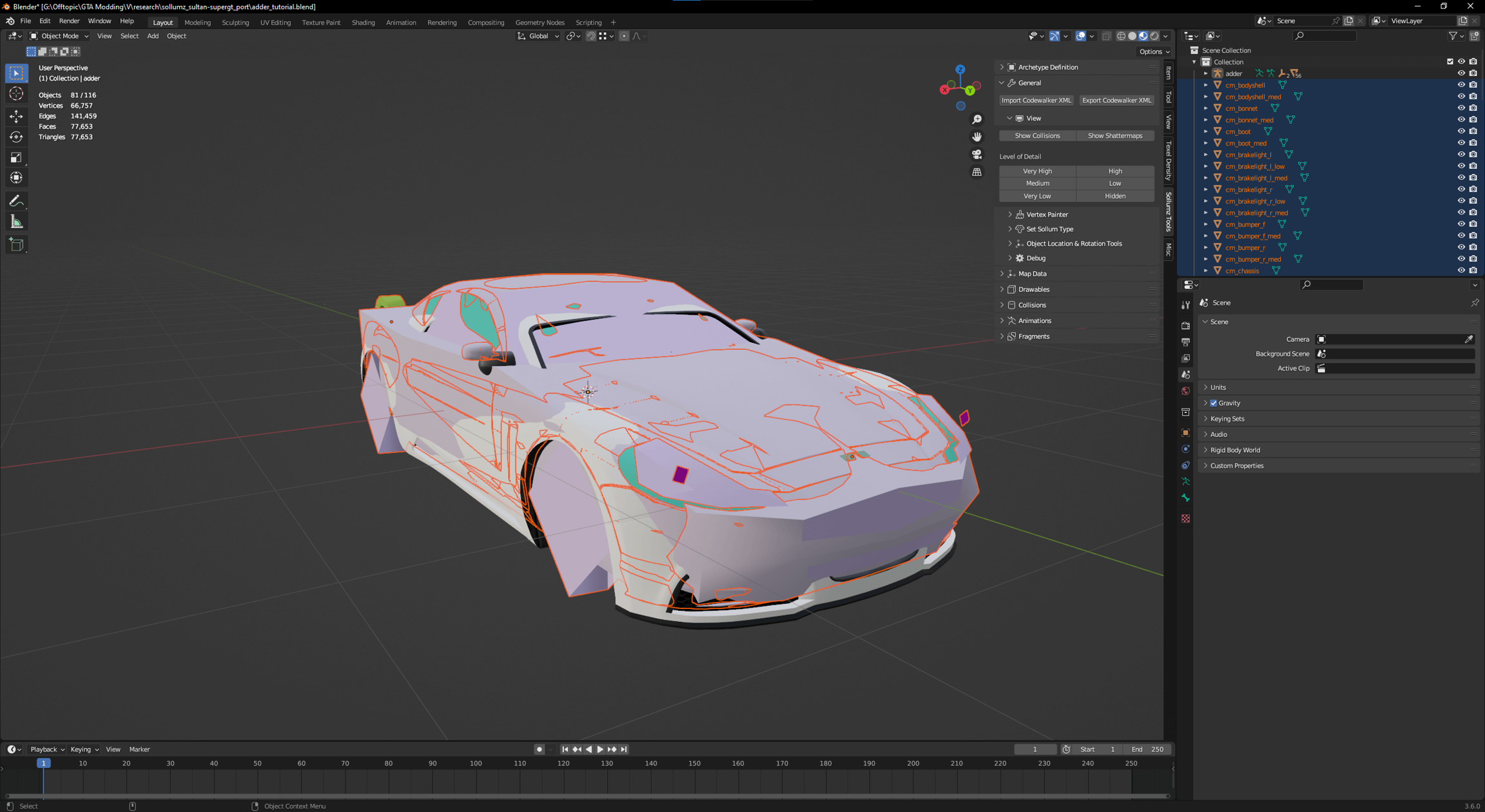
One thing you should know is that there are generally two different types of peds for GTA: "streamed" and "non-streamed". For a basic explanation, just know that peds use YDD (drawable dictionary) files for their models instead of YDR. For streamed peds, all of their 'parts' (ie shirt, shoes, head, etc) are separate YDDs. For non-streamed peds, all of those parts are put together into 1 single YDD. Streamed peds are generally easier for beginners to start with editing, because you can edit and export 1 piece at a time so if you mess up, you know it's just that 1 part that isn't working.

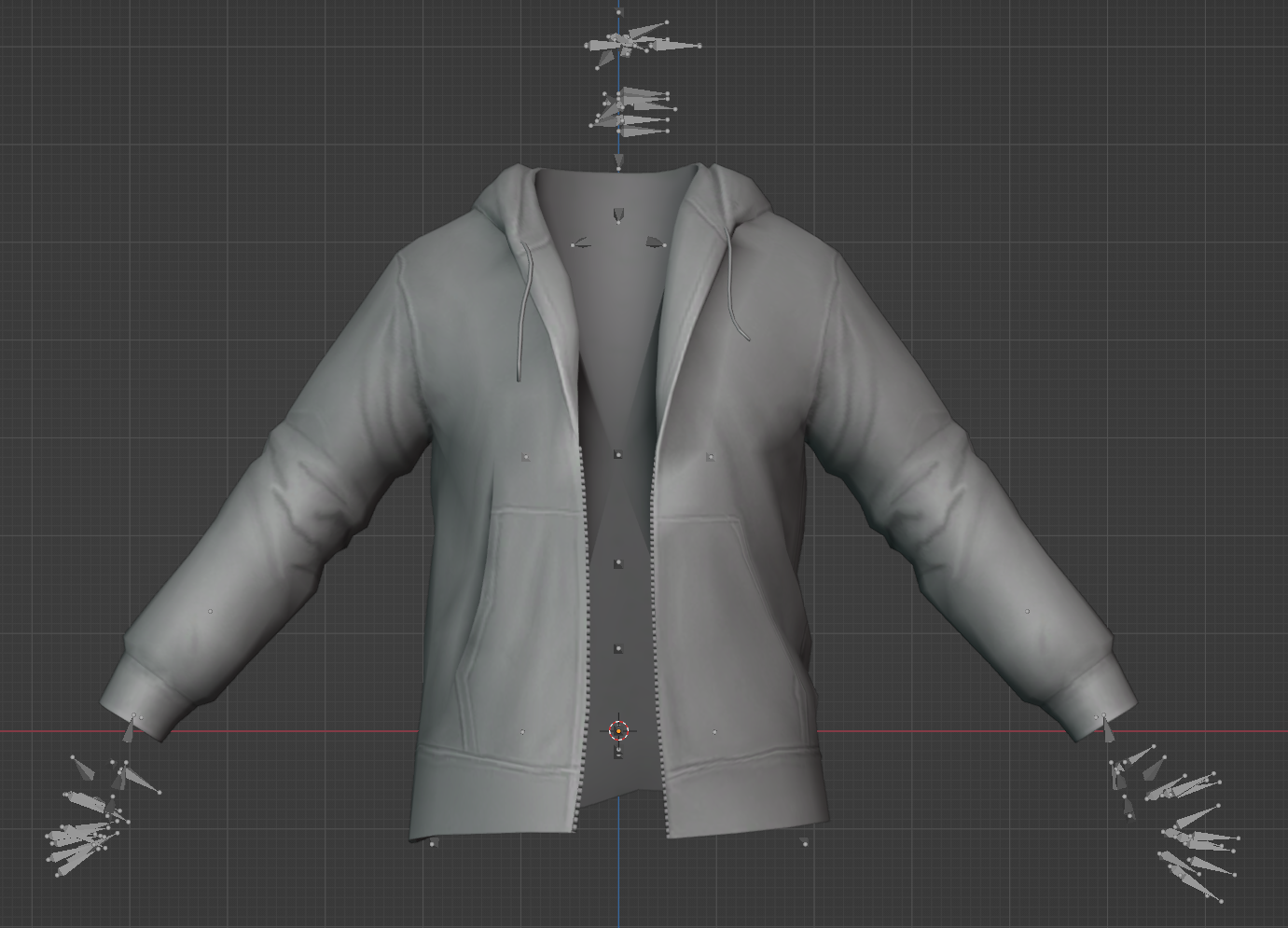
MP Freemode both male and female are both "streamed peds". This means that all of their parts are separate. If you wanted to see a 'base body' in blender to work with, you'll need to import several different YDDs: a HEAD, an UPPER, a LOWR, and a FEET.

Ped Skeletons

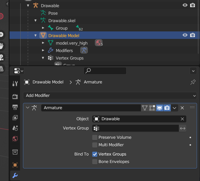
One other note before we start: All peds, whether streamed or non-streamed, have a SEPARATE FILE called a YFT for their skeleton. For whatever ped you are editing with Sollumz, you will need their YFT file so that Sollumz knows what their bones are.

Importing the Files

Export the skeleton YFT XML

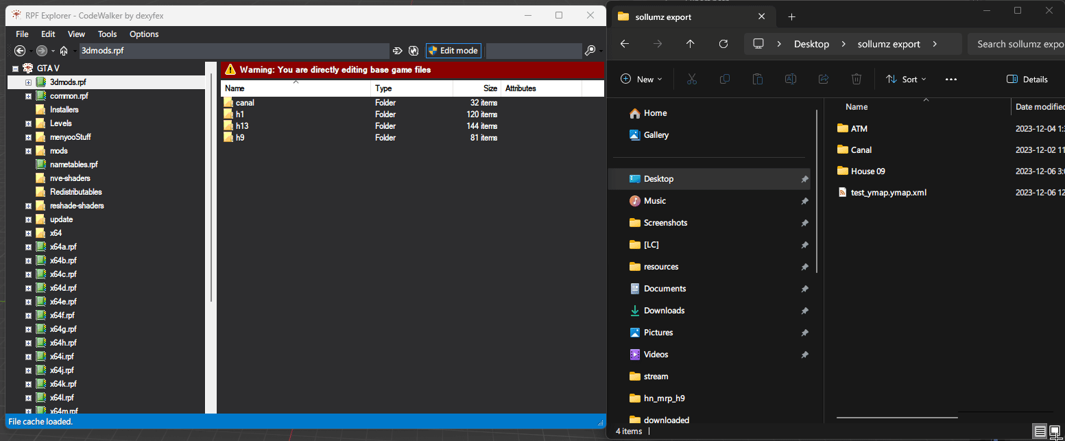
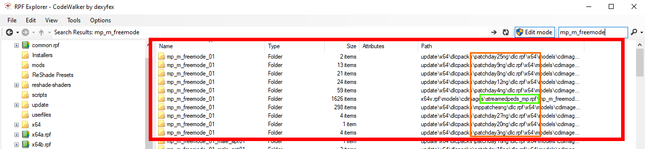
Let's start getting ready to get into Blender! The first step is to export the male and female Freemode ped skeletons (YFTs) to use when importing and exporting components that are rigged to the ped. These are located at x64v.rpf\models\cdimages\streamedpeds_mp.rpf and can be saved separately to be used with any freemode ped clothing or accessories you edit in the future.

If you haven't already created a folder somewhere on your computer to work on this project, do that now. Then, right-click the mp_m_freemode_01.yft and press Export XML.... Make sure you're keeping track of where you exported the XML to. It will need to be in the same folder as the YDD when we import into Sollumz.

Exporting the YDD

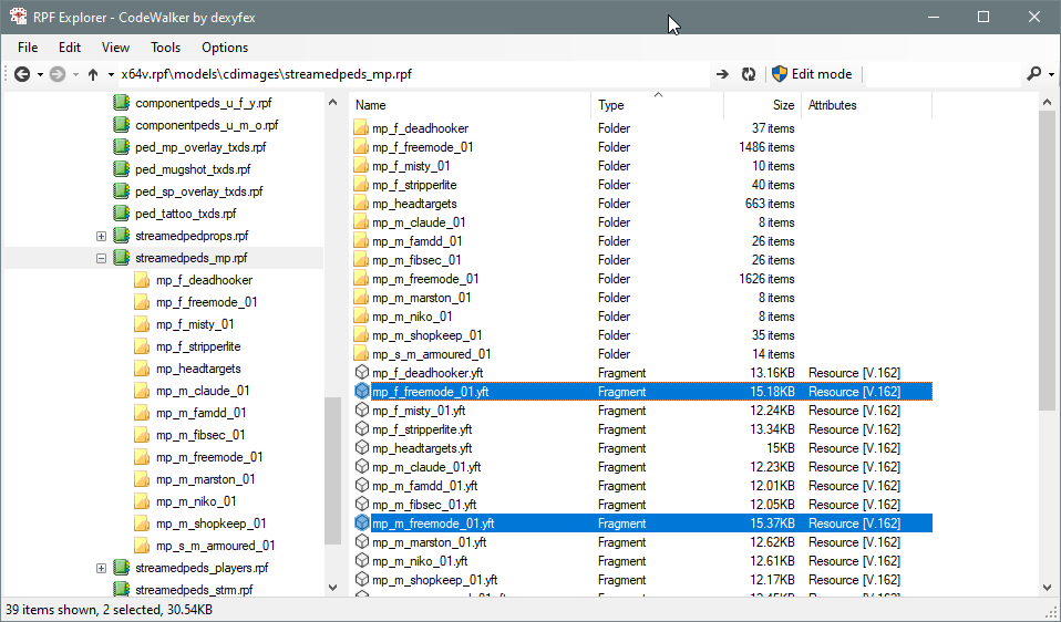
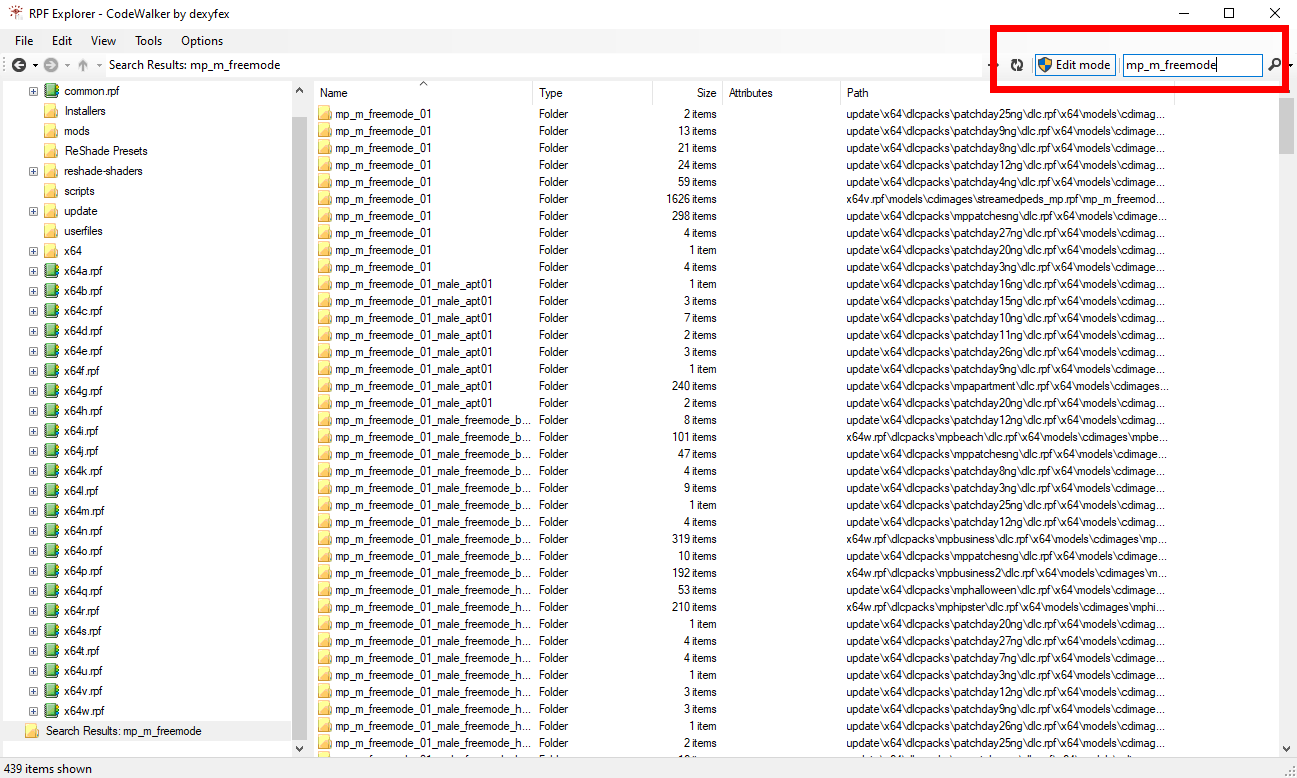
Open up CW RPF and type mp_m_freemode into the searchbar

If you click "Name" at the top to sort by name, you'll then see a list of all of the MP Male folders. You'll notice there are multiple folders for every DLC. This is the original DLC folder, and then patchday folders that hotfixed any issues R* had with various pieces of clothing.

The 🟥 outline is all of the base MP male DLC folders

The 🟧 outline highlights all of the DLC names. Notice the original DLC and all of the patchday hotfixes.

The 🟩 outlines the original base game DLC folder.

Right now we aren't going to worry about any hotfixed files, so just click into the original DLC folder. If you are ever editing GTA assets, though, you should always look through the patchday folders for whatever component you're trying to edit so that you can work off of the most up-to-date version.

Now that we're inside the base folder, you'll see a long list of all the base game components and their YTD textures. Make sure you're sorted by 'Name' so that everything is alphabetical, and then scroll down until you see the JBIBs.

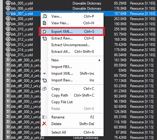
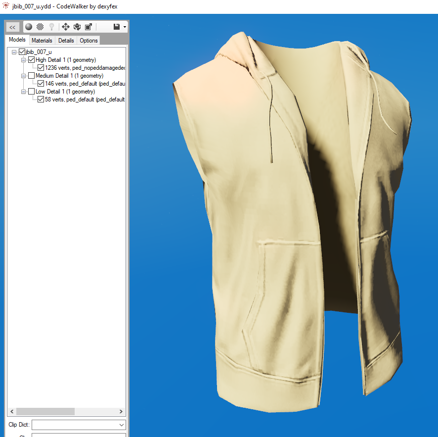
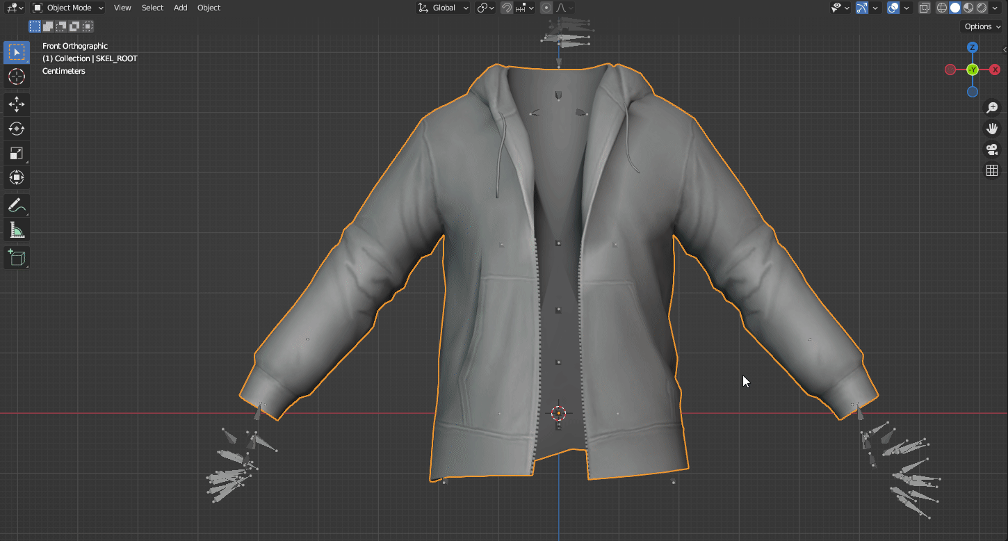
For the purposes of our tutorial, let's export jbib_007_u.

  1. Right-click on jbib_007_u.ydd

  2. Select export XML...

  3. Export location: Make sure you export to the same folder you exported the YFT earlier.

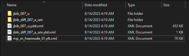
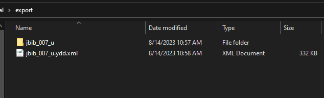
Now let's quickly visit the folder you've just exported the file to. In the folder, you should have a couple of things. Firstly the mp_m_freemode_01.yft.xml, then .ydd.xml of our jbib & there should also be a folder named jbib_007_u.

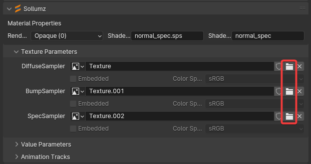
Whenever you are exporting a model that has embedded textures, Codewalker RPF will create a folder named after the model you exported to XML with all of the embedded textures placed inside of it.

Go ahead and click into the folder and take a peek at the embedded textures! You should see two: a normal texture and a specular texture. To quickly explain these: A normal helps emphasize clothing details like wrinkles & a specular helps display the glossiness or matte of your clothing.

Most freemode clothing components have an embedded specular texture and normal texture. When you go to make your own models later on, you'll need to learn how to create these yourself. For now, they have already been made for us. So get familiar with them while you can!

Exporting a texture for our model

You might have already noticed, but there's one texture we don't have yet: A diffuse texture. The diffuse texture for clothing YDDs stays un-embedded from the model and in a separate file called a YTD (texture dictionary), and you can have up to 26 of them (A to Z) for any single YDD. We don't need the texture for our editing today, but it's nice to have a visual reference, so let's grab one now.

In Codewalker RPF right below where you found the YDD we exported, should be the YTD files. Scroll down until you see jbib_diff_007_a_uni.ytd and export it to XML. It will create a sub-folder named jbib_diff_007_a_uni with the texture inside of it.

Ready for Blender

Do a final check before opening blender. Your folder should look like this:

Your .yft.xml is in the same folder on the same level as the .ydd.xml . That's the import part!

If you would like, you can copy/paste the diffuse texture from the jbib_diff_007_a_uni to the "embedded textures" folder jbib_007_u . This will allow Sollumz/Blender to automatically find the texture when you go to import. Otherwise, you can link it manually later on.

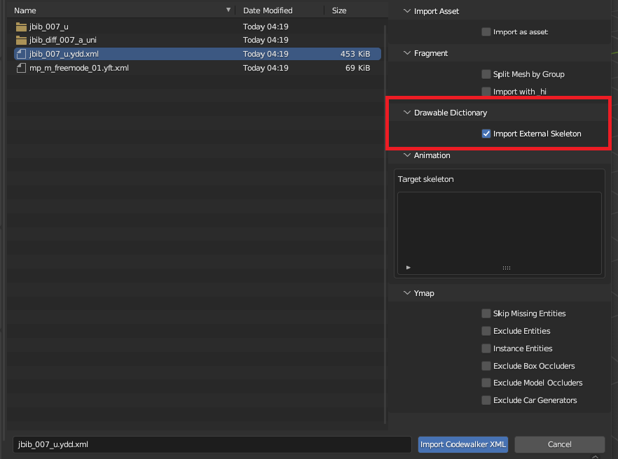
Importing to Sollumz
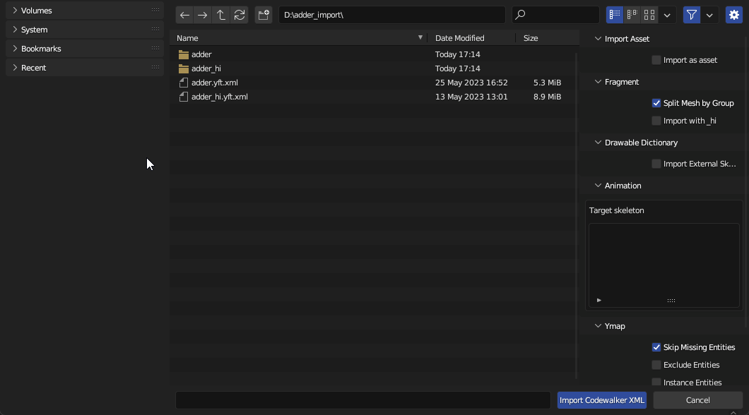
With Blender open:

  1. click File

  2. Import ► Codewalker XML

  3. Navigate to the folder you exported the XMLs

  4. Click jbib_007_u.ydd.xml and from the side-menu options make sure you select 'Import External Skeleton'

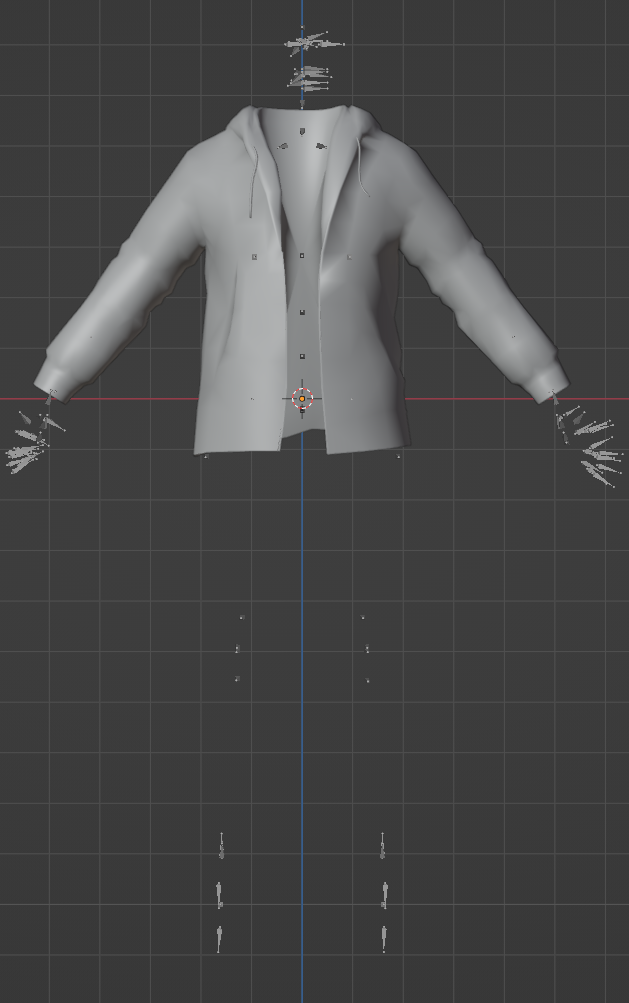
You should now be looking at something like this:

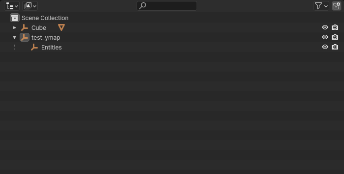
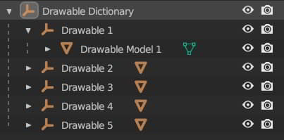
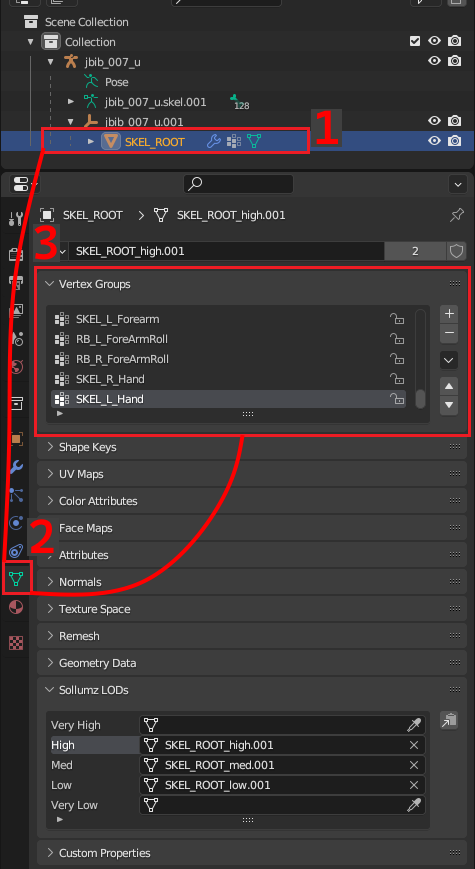
Let's make sure we imported correctly. In scene collection:

  1. Expand jbib_007_u and then jbib_007_u.001 and click on SKEL_ROOT

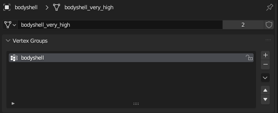
  2. In the properties window, click on the Object Data Properties tab

  3. Expand Vertex Groups (if its not already) and make sure they are all named.

If you see named bones like SKEL_L_Hand etc then you're good to go! If you see something like UNK.001 you did not follow the correct steps for exporting the YFT portion of this tutorial. Go back up, re-read, and try again.

Preparing the model

Viewport adjustments

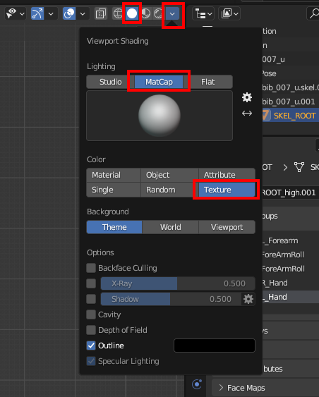
With everything imported properly, let's get ready to actually edit! First things first, we probably want to change our viewport to actually see what we're working with.

Personally, I like to change the 'color' to Texture and 'lighting' to MatCap, but you can play around in this menu and see what works for you.

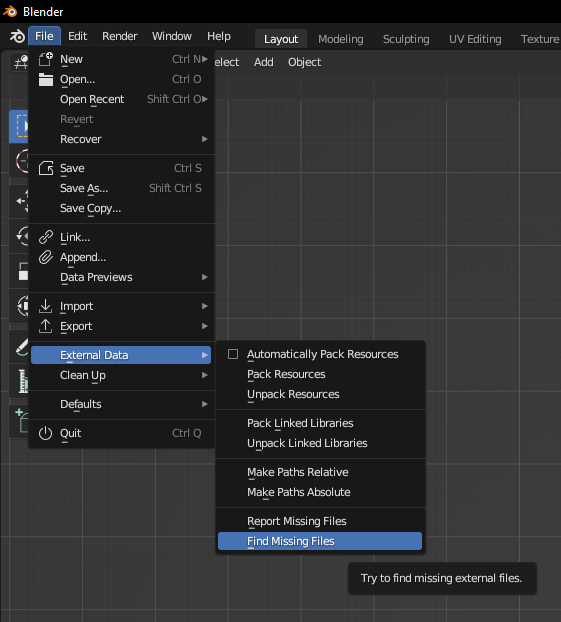
Linking diffuse texture

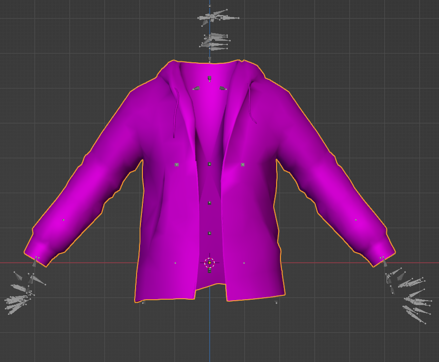
Once we have that set, your shirt might look like this:

If you left the diffuse texture in it's own jbib_diff_007_a_uni sub-folder, you'll see our jacket is pink. That's fine! We can just link up our diffuse texture now.

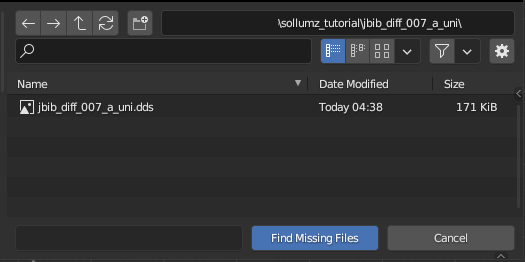
  • Top-left, go to File ► External Data ► Find Missing Files

Navigate to your project folder and select the jbib_diff_007_a_uni sub-folder where you will see the jbib_diff_007_a_uni.dds. Then press 'find missing files'.

It's good to know this method, as you will use it in other parts of Sollumz modding as well for things like props and MLOs. You might see a yellow warning popup at the bottom of your blender that says it cannot find 'givemechecker.dds' . This is fine to ignore.

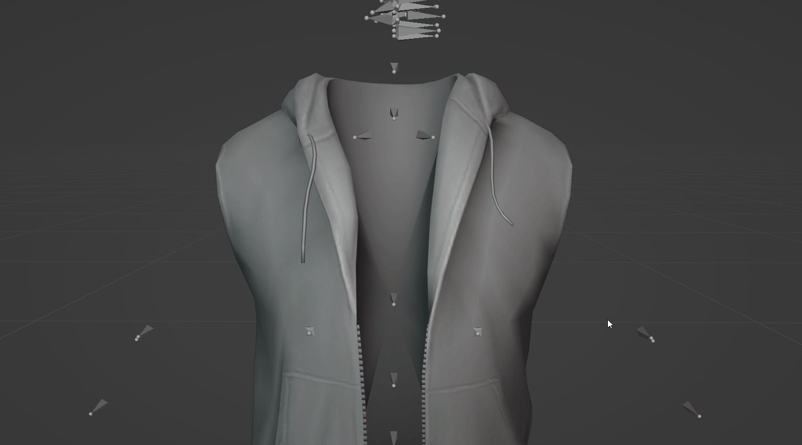
Head back to the 3D viewport (instead of shader editor) and we can see our jacket now has the diffuse texture:

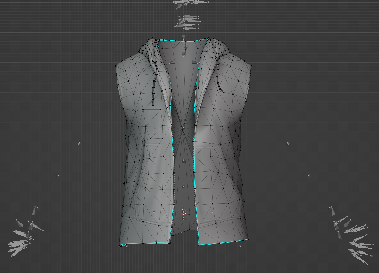
Great! Just one more thing to do before we actually edit. When importing into blender our vertices have unmerged and we've lost our sharp edges. We want all of that back so that we can have the most accurate view of what we're working with and what it will look like in-game.

Merge vertices/Sharp Edges

To fix things, let's do the following:

  1. Select SKEL_ROOT in scene collection

  2. In 3D Viewport, Tab into Edit Mode

  3. Select everything (Default: A key)

  4. Merge ► By Distance (Default: M key)

  5. In the bottom left for the 'Merge by Distance' window, expand it and tick on Sharp Edges

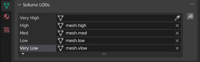
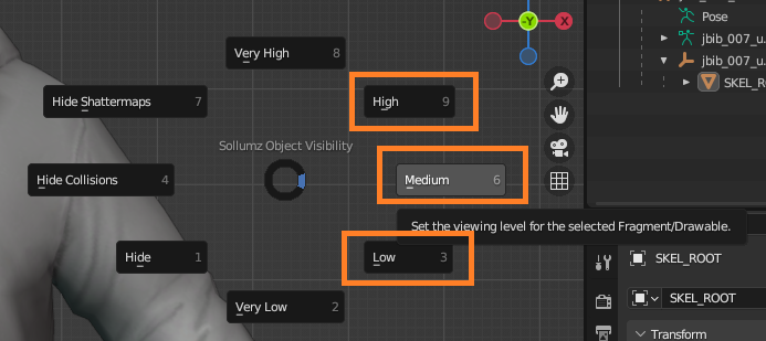
Clothing has 3 LODs (level of detail): high, medium, and low. We also need to do the same thing for our medium and low LODs.

The easiest way to switch between LODs quickly is to press SHIFT + V (make sure you are no longer in edit mode) to bring up the Sollumz Object Visibility wheel.

The three options on the right-side of the wheel are the ones you'll be using for clothing YDDs. Switch to Medium, repeat the same steps above. Then switch to Low, and do it once more.

diting

We're ready to edit! Switch back to High LOD with SHIFT + V and tab into edit mode. You can make any changes you want here. I'll delete the sleeves for the purpose of this tutorial.

Now that I've removed the sleeves, I have 2 things to resolve:

  1. I need to fill in the holes where the sleeves used to be

  2. I need to create new sharp edges to tidy up the model

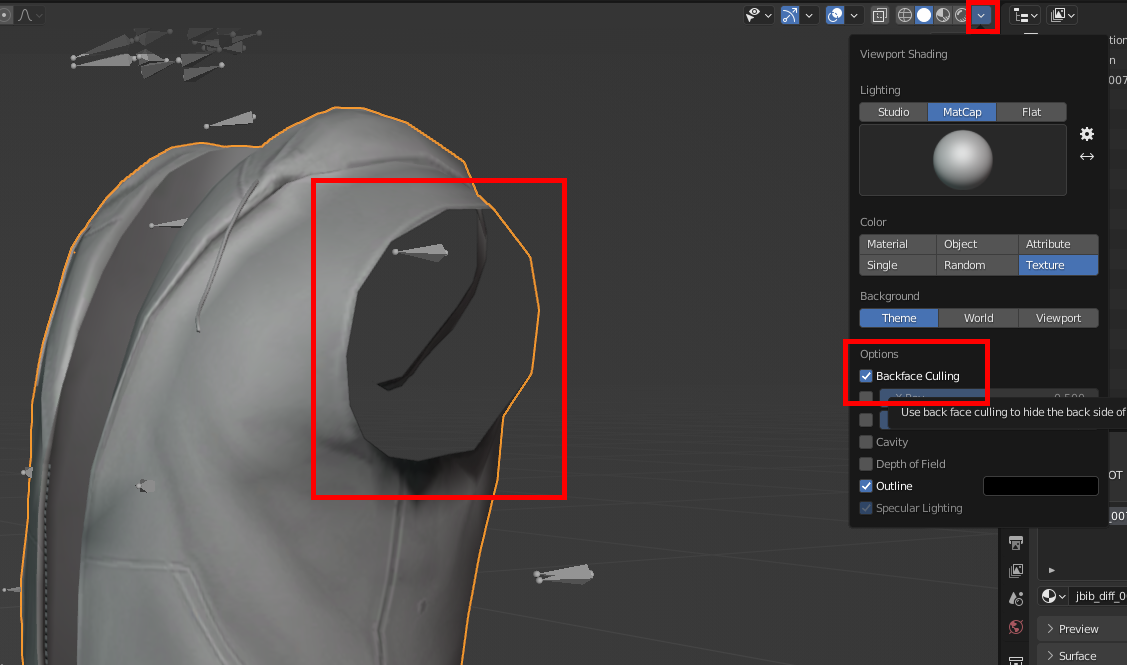
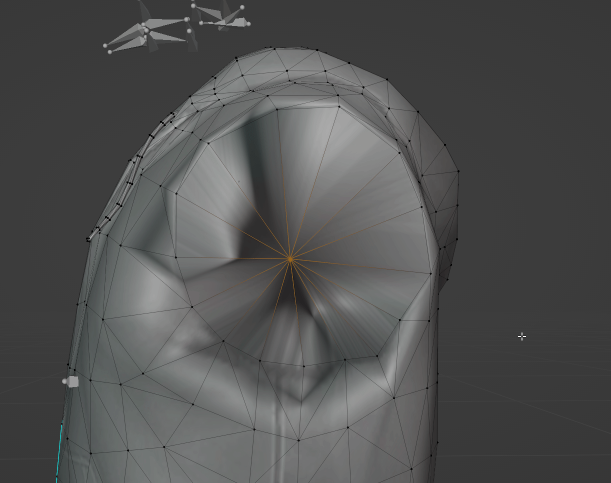
The reason we want to fill in the holes is because GTA uses back-face culling. What this means is that the faces on the model do not have both a viewable "front" and "back". Instead, the front-facing side is visible and the back is invisible. We can see this in action in blender by going back up to the viewport shading options and turning it on.

You can see the "back side" of the model is invisible now. We need to fill in those holes. There are two ways to fix this.

First, go back into edit mode and select all of the vertices around the edge.

Then you have two options. You can either press F to fill in the hole, or you can extrude the hole and then merge the vertices from the extrusion. For this tutorial, I'll be doing the second method.

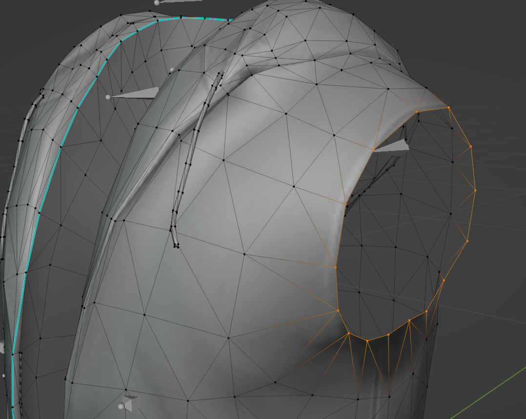
  1. Select the vertices around the edge

  2. Extrude (default E key)

  3. With your mouse, move the new points slightly inward

  4. Scale the vertices together (default S key) then merge them (M Key) ► at center

You might notice that our new geometry looks a little weird. Almost as if its shiny in places.

What's happening here is we have bad normals. To be clear, there is a difference between the embedded "normal texture" (sometimes also called a bump map) and geometry normals. If you'd like to learn more about normals, there are plenty of youtube videos that can help.

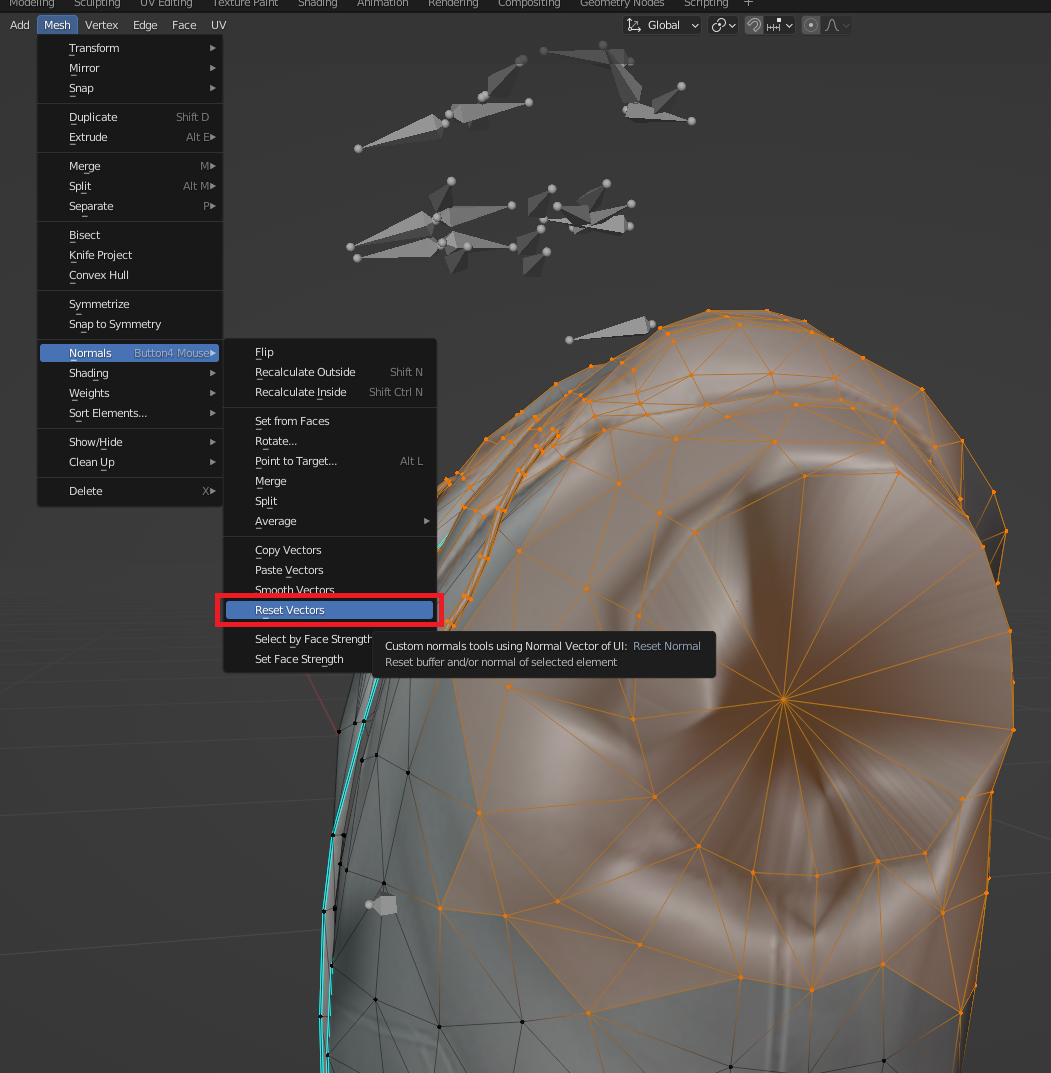
For now I'm just going to reset them to clear up this issue! With my geometry selected go to Mesh ► Normals ► Reset Vectors

Once that's done, everything should be looking much betterr.

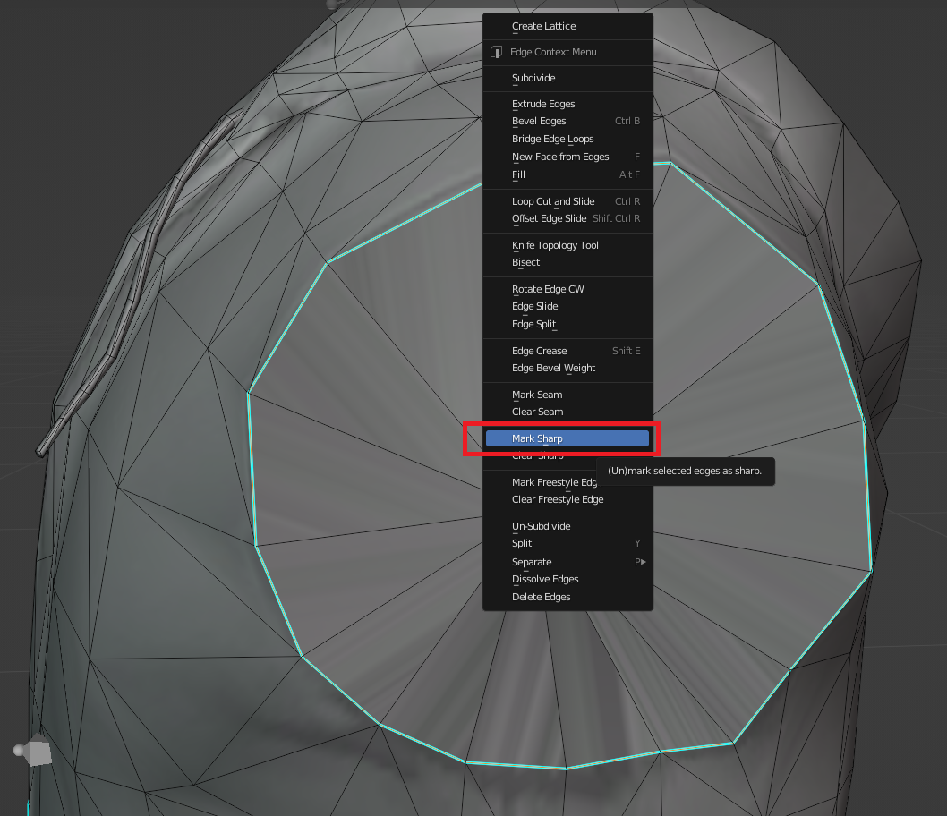
Since this is the edge of the shirt, I'd also like to set some sharp edges along the same loop we just filled in. Sharp edges add a more "crisp" line in geometry that is clearly visible in-game. When you use them properly, they can add a little extra emphasis to your model quality. There's no rule of when or when not to use sharp edges, it's up to you to follow the lines of clothing and determine where they would make sense.

For now I'll go to edge select & select the loop I filled in, then right-click and press "mark sharp"

Now do the same thing with the other side.

With that done comes the boring part: Repeating the same process with the medium and low LODs! With custom models, you would have all of this already finished before you create your LODs but when editing existing clothing, you need to either edit everything the same or create new LODs after you've edited.

For this tutorial, you should delete the sleeves on the med/low LODs so that they look visually similar, but it's up to you whether you want to fill in the sleeve holes like we did here for High LOD. Chances are that from a distance people won't be able to see that small detail anyway.

Exporting

With all of the LODs edited, we're now ready to export!

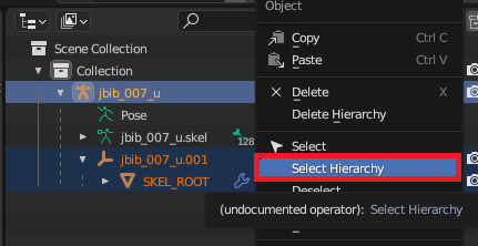
  • In the outliner window, right-click jbib_007_u and select hierarchy

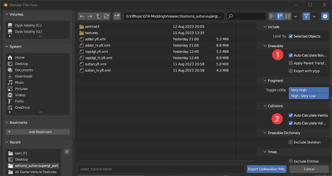
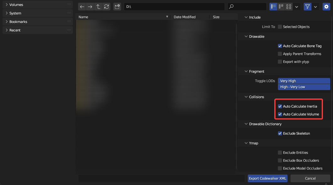
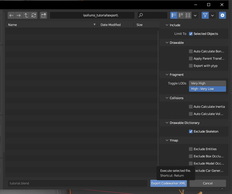
  • Then go top-left to File ► Export ► Codewalker XML

  • It's best to create an 'export' folder so that you are not overwriting the original. That way if you mess up, you don't have to go grab the ydd xml all over again.

  • navigate into Export folder

  • Export

The window will close and at the bottom of your blender you should see a message like "exported in 0.12 seconds".

Now in our export folder, we should have our new .ydd.xml and a copy of the embedded textures folder with our normal/specular textures inside.

You can now head back over to Codewalker RPF and import the XML to turn it back into a YDD & preview it!

Our model is finished! Now you can replace the existing one or create an addon with the same textures and test in-game. In-game you might see it clips with the underarms as you move around. That's due to something called "weight painting". More about that to come in future tutorials!

an image of codewalker showing the folder where mp m/f yfts can be found

Now we'll export the model we actually want to edit, as well as a texture for it. If you didn't already know of it, is a good visual reference for most of the freemode components. It has most DLC clothing, although it is missing some of the newer updates. Today we already know what clothing piece we're using, so let's head back over to Codewalker RPF and grab the file.

you can ignore this warning
an example of bad normals
tobii.space

Creating Weapons [TODO]

TODO

Basic Animation Editing [TODO]

TODO

Vertex Groups, Hierarchy, and Armature

Create and assign Vertex Groups

To create a new vertex group, go to Data tab, click + in Vertex Groups, double click on the Group name and rename it to bonnet.

  1. Change Object Mode to Edit Mode.

  2. Switch to Face Select.

  3. Select all faces by pressing A or using the CTRL+A shortcut.

  4. Go to Vertex Groups, click Assign button and exit Edit Mode.

Now all of the selected faces are properly set to the bonnet vertex group.

Hierarchy

Our new custom bonnet model has to be considered by Sollumz as a valid part, so we have to move the mesh by expanding Adder's armature then drag and drop bonnet's Drawable Model inside adder.mesh

You can delete the original bonnet, since is not needed anymore.

Armature

A replacement custom part has also to be linked to the armature, you can do this via Armature modifier.

  1. Go to Modifiers tab.

  2. Add an Armature modifier.

  3. Select your vehicle's armature.

Rigging

Drawables can be rigged using either vertex groups (skinning) or Child Of constraints. The top-level Drawable object must be an armature.

Skinning

Skinning Drawables works the same way you would normally do it in Blender. Simply create vertex groups where each group's name corresponds to a bone in the armature. Then, add an armature modifier and specify the Drawable as the armature object.

Linking bones to Drawable Models

Many Drawables aren't rigged using weighted vertex groups. You can instead link an entire Drawable Model to a bone by using a Child Of constraint.

Use the "Add Bone Constraint" operator with the Drawable Model Selected to add a Child Of Constraint with the properties setup for correct previewing.

By default, Blender sets the owner space and target space of the Child Of constraint to "World" (can be edited in the Sollumz sub-panel of the Child Of constraint). This can cause issues when objects are parented to both bones and other objects. Because of this, make sure to always use the Add Bone Constraint tool when creating Child Of constraints.

Drawables (.ydr)

File Layout

Drawable
    ShaderGroup
        Shaders
        TextureDictionary
    Skeleton (sometimes)
    DrawableModelsHigh
        Geometries...
    DrawableModelsMed
        Geometries...
    DrawableModelsLow
        Geometries...
    DrawableModelsVeryLow
        Geometries...
    Lights (sometimes)

Drawables consist of multiple "Drawable Models" which hold the actual mesh data. Drawable Models are organized into High, Medium, Low, and Very Low detail levels. In every Drawable there is also a list of the shaders used and the parameters for each shader. Sometimes there are textures embedded in the file as well. Drawables can also contain skeleton data, but it is not required. This is usually only found in dynamic Drawables (objects affected by physics) such as props or in Drawables that are animated. Lastly, Drawables can contain lights, where each light contains light properties such as direction, falloff, color, etc.

Blender Hierarchy

In Blender, the hierarchy for Drawables consists of one parent Drawable object (either an empty or an armature depending on whether or not the Drawable has skeleton data) and Drawable Models (mesh objects).

Converting To Drawable

Converting to a Drawable

The first thing to do is convert your object(s) to a Drawable. Select all the objects and click Convert to Drawable in Sollumz Tools > Drawables > Create Drawable Objects.

You will notice in your Scene Collection top right, that your object has changed a little. It is now in the correct hierarchy / format for GTA V.

Process of creating a vertex group
Assignment of faces to vertex group
Bonnet part moved into adder.mesh
Removal of vanilla bonnet part of adder.
Armature modifier creation
Drawable Model setup for skinning
Sollumz Tools > Drawable > Bone Tools
Example Child Of Constraint for a Drawable Model

Drawables are objects that hold mesh data, skeleton data, and shader data. It can be thought of as the game engine's mesh format. YDR files contain one Drawable and are typically used for static mapping but are also used for dynamic props in some cases. In cases where a prop consists of multiple breakable parts, objects are used instead.

Example Drawable object

Game meshes are stored in the file format. Creating Drawables in Sollumz is very simple. This tutorial will walk you through step-by-step.

Drawable Hierarchy

If you navigate to Mesh Properties > Sollumz LODs with the drawable model selected, you'll also notice that the active mesh is automatically assigned to the "High" LOD level. This panel is where you can assign other meshes as LODs. More info on that . For the sake of this tutorial, we will only be setting the High LOD level.

Mesh Properties > Sollumz LODs
Fragment (.yft)
Drawable (.ydr)
here

Import Settings

There are two import settings that determine how Fragments import: Split By Group and Import with _hi.

Split By Group

Here is what adder.yft looks like when split by group.

Notice how each object represents a separable part of the vehicle. Since it's split by vertex group, each object will only have one vertex group.

While the Drawable is initially set up with one vertex group per object, it is perfectly fine for an object to contain multiple vertex groups.

Each object also has an armature modifier with the Fragment as the target object.

Import with _hi

Vehicle Fragments have an additional LOD level that is stored in a separate file named <fragment name>_hi.yft. For adder, it would be called adder_hi.yft. This is the highest level of detail and is what the player sees when close to the vehicle (i.e. when driving). It is very cumbersome to work on two separate YFTs so Sollumz stores this extra LOD level in the Very High LOD level. This enables you to work on both YFTs at once.

You should only use this LOD level when working with vehicles. When a mesh is provided for the Very High LOD level, Sollumz will export an extra _hi YFT that you don't need when working on props.

As with any Fragment/Drawable, if you want the textures to be automatically imported with the mesh, ensure you extract all textures to a folder with the same name as the Fragment in the same directory.

Import Codewalker XML > Fragment

Split By Group will split the Drawable by vertex group. This is typically what you want when editing vehicles, as vehicles are skinned (i.e. rigged with weighted vertex groups), so there is typically only one Drawable Model containing many vertex groups as opposed to multiple Drawable Models each linked to a bone (see for more info on rigging Drawables).

adder.yft split by vertex group
bodyshell

To import Very High LODs, first enable the Import with _hi option in the, and ensure the _hi YFT is in the same directory as the non-hi YFT. Then, select the non-hi YFT and import.

Importing adder.yft.xml with hi
Drawables > Rigging > Skinning
import settings panel

Bone Physics

You will notice that each Fragment bone now has a Use Physics property.

Enabling this will reveal a Physics subpanel where various physics properties can be configured for that bone. The defaults work great for most use cases but feel free to tweak them to get the results you want.

If you're ever not sure what physics properties to set, import a similar model from the game and copy its physics properties.

Fragments (.yft)

Fragments are objects that contain separable parts and react to physics. These objects are typically used in breakable props (i.e. street lamps) and vehicles. The file contains a Drawable and a Composite (collision), and sometimes multiple of each if there is a destroyed variant such as in gas tanks. However, Sollumz does not currently support editing destroyed variants of Fragments.

It's recommended that you read the documentation page on Drawables and collisions first, as Fragments are made up of these objects.

File Layout

Fragment
    Drawable
    DrawableDamaged (sometimes)
    Physics
        Composite
        CompositeDamaged (sometimes)
        PhysicsGroups
        PhysicsChildren
    VehicleGlassWindows
    GlassWindows (currently not supported)
    Lights

The file layout for Fragments is quite complex, even with the simplified layout shown above (if you wish to see the full file layout, just open a yft.xml). However, you don't need to understand how the file works internally to understand how it works in Sollumz.

The Fragment contains a main Drawable as well as a Physics section which contains the collisions and physics data. PhysicsGroups contains groups of physics data where each group is linked to a bone. This is essentially the physics properties for each bone. PhysicsChildren contains physics data for each collision (i.e. mass, inertia). Each physics child belongs to a PhysicsGroup, and multiple children can belong to a single group.

You'll also notice there is a VehicleGlassWindows section. As the name implies, this is where data relating to vehicle windows are stored. Non-vehicle fragments can also have GlassWindows, but that is not currently supported by Sollumz.

Finally, there are Lights, which, just like Drawables, contain any lights that the Fragment might have (only ever used in prop Fragments).

Blender Hierarchy

The Blender hierarchy for Fragments is quite simple. The Fragment object itself is an armature with a Bound Composite and Drawable parented to it. The Fragment can also contain lights. Lights are typically stored in an empty object called "Lights", but can also be stored loosely in the Fragment or under the Drawable. It's up to you where to store the lights, as, during export, it will search all children (recursively) for lights. The hierarchy for the Bound Composite and Drawable is exactly the same.

Bone Properties > Sollumz > Fragment

Most importantly, enabling Use Physics is what causes the bone to react to physics. If this is unticked, any geometry associated with the bone will always remain static in-game. Usually, you'd have a bone for each separable part. That way, all parts of your Fragment will act independently of each other. See the page for an example (vehicles also have separable parts but the bone hierarchy is usually much more complex).

Strength is what determines how easily the part can be separated. If strength is -1, the part will not separate, but will still react to physics. This can be seen in props with hinging doors such as the container prop shown in .

Example Fragment object
Prop Setup
https://github.com/Sollumz/wiki/blob/main/documentation/drawables.ydr
💥Collisions (.ybn)

Collision Physics

Each separable part of a Fragment must have an associated collision object in order for physics to work. This means each bone with Use Physics enabled should also have a collision object linked to it.

Rigging Collisions

Setting Mass

Each collision object under a Fragment also has a Physics subpanel where you can define its mass.

Auto Mass Tool

There is also a tool for automatically calculating mass based on the collision material's density and the object's volume. Navigate to Sollumz Tools > Fragment > Set Mass. There you will find the Calculate Collision Mass tool.

In order for this tool to work, the collision object must have a collision material added.

Volume and Inertia

Volume and Inertia are essential physics properties for collisions. You can find these options under Object Properties > Sollumz.

Typically when creating completely custom collisions, you would auto-calculate these values during export, as calculating these involves a lot of math relating to the dimensions and shape of your collisions.

Level of Detail (LODs) Editing

Setting LOD Level

For each LOD level, you can select the mesh it will use. You can also select any LOD level from the list and it will swap out the mesh that the Drawable Model uses.

LODs can also be changed for the entire hierarchy at once in the Sollumz Tools > General > View panel.

Alternatively, press Shift + V to open a pie menu for quickly viewing different LOD levels.

Auto LOD Tool

Sollumz provides a basic LOD generation tool that uses the decimate modifier.

Select the Drawable Model and Navigate to Sollumz Tools > Drawable > LOD Tools.

From here you can select which LOD levels will get created. Normally you'd model the highest LOD first, convert to a Drawable Model, then use that high LOD mesh as the reference mesh. The reference mesh is not affected in this process. Each subsequent LOD level is decimated by Decimate Step.

Your results will vary depending on the mesh, as the decimate modifier does not work well for all topologies.

Extracting LODs into Separate Objects

You can also take advantage of Blender's instancing functionality and separate the LOD meshes into separate objects. This allows you to work on multiple LOD meshes at once.

Select the Drawable Model and Navigate to Sollumz Tools > Drawable > LOD Tools.

From here you can select which LODs to extract as well as what to parent the new objects to. You can either parent the objects to a collection or an empty object.

Notice how these new objects are using the same meshes as the ones defined in the Sollumz LODs panel.

Now, if you edit one of these object instances, the Drawable Model will be affected too.

Vehicle Setup

The example vehicle used in this article is adder.yft

Fragment Hierarchy

Contents

Paint Colors

Paint colors allow you to determine which materials represent the Primary color, Secondary color, Wheel color, Interior Trim color, and Dashboard color. To select the paint color for a material, navigate to Material Properties > Sollumz > Fragment.

By default it will be "Not Paintable", meaning the shader will not be affected by any paint color.

Not all shaders are paintable. If you are trying to set up a paintable vehicle material and you are getting the "Not a paint shader" message, then you need to use a different shader. Typically you'd want to use a vehicle_paint shader for the body of a vehicle.

You link collisions to bones the same way you link Drawable Models to bones as described in .

Collision object linked to bone via a Child Of constraint
Object Properties > Sollumz > Physics
Sollumz Tools > Fragment > Set Mass
Object Properties > Sollumz
Export Codewalker XML > Collisions

The LODs for each Drawable Model can be edited in the Mesh Properties > Sollumz LODs panel. As mentioned before, there are 4 LOD levels: High, Medium, Low, and Very Low. You will also see the "Very High" LOD level, but that is only used for YFT vehicles (see Fragments > ).

Mesh Properties > Sollmz LODs
Swapping LOD meshes
Sollumz Tools > General > View
LODs pie menu (Shift + V)
Sollumz Tools > Drawable > LOD Tools
Generating LODs using Suzanne.high
Sollumz Tools > Drawable > LOD Tools
Extract LODs
Mesh Properties > Sollumz LODs
Editing Suzanne.high
adder.yft
adder.yft Blender hierarchy
Vehicle Windows
Light IDs
Paint Colors
Export Settings
Drawables (.ydr) > Rigging
Vehicle Setup
Material Properties > Sollumz > Fragment

Vehicle Shaders

In this page you can find all vehicle shaders used on vehicles and their technical usage

Vehicle Paint shaders

vehicle_paint1

Texture samplers: Diffuse, Dirt, Specular / DiffuseSampler, DirtSampler, SpecSampler

UV Maps: UV Map 0 - Diffuse/Specular UV Map 1 - Dirt

vehicle_paint1_enveff

Texture samplers: Diffuse, Snow Sampler 0, Snow Sampelr 1, Dirt, Specular / DiffuseSampler, SnowSampler0, SnowSampler 1, DirtSampler, SpecSampler

UV Maps: UV Map 0 - Diffuse/Specular UV Map 1 - Dirt Vertex Alpha: visibility of snow samplers

Vehicle Light shaders

vehicle_lightsmeissive

Texture samplers: Diffuse, Dirt, Specular / DiffuseSampler, DirtSampler, SpecSampler

UV Maps: UV Map 0 - Diffuse/Specular UV Map 1 - Dirt

Vehicle Glass shaders

todo

Vehicle Interior shaders

vehicle_interior

Texture samplers: Diffuse, Specular / DiffuseSampler, SpecSampler

UV Maps: UV Map 0 - Diffuse/Specular

vehicle_interior2

Texture samplers: Diffuse, Specular / DiffuseSampler, SpecSampler

UV Maps: UV Map 0 - Diffuse/Specular

Vehicle Mesh shaders

vehicle_mesh

Texture samplers: Diffuse, Dirt, Bump, Specular / DiffuseSampler, DirtSampler, BumpSampler, SpecSampler

UV Maps: UV Map 0 - Diffuse/Bump/Specular UV Map 1 - Dirt

Vehicle Tire shaders

vehicle_tire

Texture samplers: Diffuse, Dirt, Bump, Specular / DiffuseSampler, DirtSampler, BumpSampler, SpecSampler

UV Maps: UV Map 0 - Diffuse/Dirt/Bump/Specular

Vehicle Emissive shaders

vehicle_dash_emissive

Texture samplers: Diffuse, Specular / DiffuseSampler, SpecSampler

UV Maps: UV Map 0 - Diffuse/Specular

vehicle_dash_emissive_opaque

Texture samplers: Diffuse, Specular / DiffuseSampler, SpecSampler

UV Maps: UV Map 0 - Diffuse/Specular

Vehicle License plate shaders

vehicle_licenseplate

Texture samplers: Dirt, Plate background, Place background bump, Font, Font bump / DirtSampler, PlateBgSampler, PlateBgBumpSampler, FontSampler, FontNormalSampler

UV Maps: UV Map 0 - Plate background, Place background bump, Font, Font bump UV Map 1 - Dirt

Vehicle Miscellaneous shaders

vehicle_badges

Texture samplers: Diffuse, Bump, Specular / DiffuseSampler, BumpSampler, SpecSampler

UV Maps: UV Map 0 - Diffuse/Bump/Specular

vehicle_decal

Texture samplers: Diffuse, Specular / DiffuseSampler, SpecSampler

UV Maps: UV Map 0 - Diffuse/Specular

vehicle_detail2

Texture samplers: Diffuse, Detail, Specular / DiffuseSampler, DetailSampler, SpecSampler

UV Maps: UV Map 0 - Diffuse/Bump/Specular UV Map 1 - Detail (tileable)

Vehicle Windows

Vehicle windows are defined in the physics properties of the window collision. See window_lf.col in adder.yft for example.

Enabling Is Glass Window will cause the window properties to appear. The only property you should have to change here is the Window Material. This is the material that the corresponding window mesh uses. Looking at the window_lf mesh materials, we see that it uses two vehicle_generic_glasswindows2 materials.

This is because one material represents the inner glass and the other represents the outer glass. Go into Edit Mode and select the vertices of each material to see which one represents the outer glass. In this case, it's the material without the ".001" so that's the one that the glass window should reference.

That's all that is needed for working vehicle windows!

Shattermaps

You will notice that all vanilla vehicles have "shattermaps", which is an image that defines the border of the glass-breaking pattern. These aren't 100% necessary for working vehicle windows but will result in better-looking glass shatter patterns.

In Sollumz, shattermaps are represented as planes with a single texture. For example, adder.yft has an object called windscreen_shattermap which is parented to windscreen.col.

These are always low-res bitmap greyscale textures. Currently, Sollumz has no tools for creating shattermaps, so your best bet is to copy shattermaps from vanilla files and work off of those.

Light IDs

Any mesh with vehicle_lightsemissive shaders will appear always emissive in-game unless light IDs are assigned. Assigning light IDs allow you to make some faces only appear emissive under certain conditions (i.e. headlights on/off). Sollumz makes assigning light IDs easy.

With a headlight object selected, enter Edit Mode in Face Selection mode and navigate to the Sollumz Tools > Fragment > Vehicle Light IDs panel.

Select the faces of the left headlight that use the emissive shader, then set its light ID to headlight_l.

Notice now that if you unselect those faces, and select the headlight_l light ID, it will select those faces you just assigned.

window_lf.col | Object Properties > Physics
window_lf | Materials
Determining which material is the outer glass material
windscreen_shattermap
Sollumz Tools > Fragment > Vehicle Light IDs
Setting left headlight light IDs
Selecting light IDs

Files not supported by Sollumz

Not every file type found in GTA is supported by Sollumz.

Ped YFTs (.yft) with articulated skeletons

Skeleton yfts (like mp_f_freemode_01.yft) are supported, as they just contain skeletons. However, some ped yfts also contain additional unknown physics data which is not handled by Sollumz. Here is a list of ped yfts that are not supported.

z_z_alien.yft 
z_z_fred.yft 
z_z_fred_large.yft 
z_z_wilma.yft 
z_z_wilma_large.yft 
a_c_boar.yft 
a_c_cat_01.yft 
a_c_chickenhawk.yft 
a_c_chimp.yft 
a_c_cormorant.yft 
a_c_cow.yft 
a_c_coyote.yft 
a_c_crow.yft 
a_c_deer.yft 
a_c_dolphin.yft 
a_c_fish.yft 
a_c_hen.yft 
a_c_humpback.yft 
a_c_killerwhale.yft 
a_c_pig.yft 
a_c_pigeon.yft 
a_c_poodle.yft 
a_c_pug.yft 
a_c_rabbit_01.yft 
a_c_rat.yft 
a_c_rhesus.yft 
a_c_seagull.yft 
a_c_sharkhammer.yft 
a_c_stingray.yft 
a_c_westy.yft 
a_c_whalegrey.yft 
a_c_chop.yft 
a_c_husky.yft 
a_c_mtlion.yft 
a_c_retriever.yft 
a_c_rottweiler.yft 
a_c_sharktiger.yft 
a_c_shepherd.yft 
a_c_chimp_02.yft 
a_c_rabbit_02.yft 
a_c_panther.yft 
a_c_chickenhawk.yft 
a_c_rhesus.yft 
a_c_seagull.yft 
a_c_chop_02.yft 
a_c_chickenhawk.yft 

Cloth Physics (.yld) files

Cloth physics files, including .ydds that require .yld, are not yet supported by Sollumz.

Drawable Dictionary (.ydd)

The Drawable Dictionary is a container that holds a collection of drawables. Its primary use is for storing LOD models, ped components, ped props, mesh minimaps and instanced props.

It is recommended that you read the Drawable documentation page before creating a Drawable Dictionary, as it consists of drawables.

File Layout

Drawable Dictionary
    Drawable#1
        ShaderGroup
        Skeleton (sometimes, mostly seen on ped components)
        DrawableModelsHigh
        DrawableModelsMed
        …
    Drawable#2
    Drawable#3
    Drawable#4
    Drawable#5
    …

For the hierarchy, several drawables exist as regular game-ready assets, but all of them share one parent drawable dictionary object.

Blender Hierarchy

In Blender, Drawable Dictionaries comprises a parent object and one or more drawable objects in its hierarchy.

Limitation

Some features of Drawable objects cannot be inherited by Drawable Dictionaries. For example, the embedded collision cannot function when the drawable is in a drawable dictionary.

Furthermore, CodeWalker cannot identify the real name of a drawable in drawable dictionaries unless a nametable with resolved names is loaded. Thus, it is recommended to create a nametable whenever utilizing a drawable dictionary in your project to facilitate your own and others' modding processes.

Archetype Definition

A Drawable Dictionary does not have its own archetype definition.

When creating the archetype definition for a drawable in a drawable dictionary, it is necessary to fill the correct name of your drawable dictionary in the "Drawable Dictionary" blank to ensure it workds within the game.

For instance, if we have the drawable dictionary my_ydd and the drawable my_ydr in the scene. Then you should fill in "Drawable Dictionary" in the archetype as shown in the picture below:

If you use the "Auto-Create From Selected" function, the "Drawable Dictionary" will be filled in automatically.

Collisions (.ybn)

Collisions are well, collisions. whether that is for players, bullets, vehicles etc. There is 3 main types of .ybns, the normal version(s), hi@ versions which is for weapon bullets, and ma@ collisions that are used to procedurally spawn grass and other things like garbage on the street.

BoundComposite
     BoundGeometryBVH
          BoundPolyMesh
          BoundBox
          BoundPolyBox

A very common mistake users make is not applying a Flag Preset to the Bound GeometryBVH, resulting in the collision not working in game.

Example Drawable Dictionay object
Fill the "Drawable Dictionary" with the name of your drawable dictionary

The Bound Composite is the top most part of the hierarchy, it doesnt control much on its own. The Bound GeometryBVH controls things like which things collide with the Bound Poly Mesh / Boxes. You can disable or enable certain flags here t o disable collision for specific object types. The Bound Poly Mesh / Box is the collision model itself, what you are actually colliding with. It is here where you can add or remove Collision materials and apply flags to said materials to control the physics of the collisions further. Also, the "Procedural ID" setting is used mainly for ma@ collision ybns to spawn procedural objects like trash on the ground. The "Room ID" Setting is used for setting up different rooms for MLOs.

https://github.com/Sollumz/wiki/blob/main/documentation/drawables.ydr

Clip Dictionary (.ycd) [TODO]

TODO

Prop Setup

Prop Setup

The example prop used in this article is prop_container_05a.yft

Fragment Hierarchy

Prop Rigging

You'll also notice that each Drawable Model is rigged using a Child Of constraint instead of vertex groups.

This is the case for all props. Typically each Drawable Model for a prop corresponds to a particular separable part of the Fragment. Notice there is a Drawable Model for the latch, each door, and the container itself.

Skeleton Setup

This matches up with the bone hierarchy.

Each bone is parented to Prop_Container_05a and is thus affected by that bone. Every skeleton in the game engine always has one root bone that all the other bones are parented to.

If you attempt to add multiple top-level bones (bones with no parent) you will run into issues. Make sure there is a single "root" bone that all other bones are parented to!

Notice, too, that each bone has Use Physics enabled. This means that each of those parts will have physics in-game and will separate from each other.

In this case, the doors don't actually "separate" from the mesh, but fling open instead. This is because the Strength bone physics property is set to -1. When set to another value (i.e. 100) you'll notice that the parts will separate.

Collisions

As mentioned before, each bone with physics enabled must have an associated collision. However, there can be multiple collisions for a single bone. Notice for this prop, there is a single collision for the latch and the doors, but the container itself is comprised of 5 box collisions.

You will notice that a lot of vanilla collisions will use bound shapes wherever possible. This is typically preferred over using a bound mesh as it is much more performant. Keep collisions as simple as possible.

Each of these collision objects is linked to a bone via a Child Of Constraint.

Each collision also has its mass set in the Object Properties > Sollumz > Physics panel.

Quick Note on YTYP Flags

In order for physics to work for your prop in-game, make sure the YTYP archetype has the "Dynamic" flag enabled!

prop_container_05a.yft
prop_container_05a Blender hierarchy
prop_container_05a.mesh
prop_container_05a.skel
With Strength set to 100 for both doors
prop_container_05a.col
Prop_CDoor_L.col constraints panel
Object Properties > Sollumz > Physics
Archetype Definition > Archetypes > crate > Flags

Wheels

Upon importing, you will notice that the vehicle has only one wheel. This is because the game instances (re-uses) wheel_lf for all other wheels.

Also, wheel meshes have the Is Wheel Mesh property ticked under Object Properties > Sollumz.

That's all that's needed for setting up wheel meshes!

Previewing the Other Wheels

In Sollumz Tools > Fragment > Create Fragment Objects is a tool called Generate Wheel Instances. This tool will create instances of the wheel, allowing you to better preview what it looks like in-game. This is useful when positioning the wheel bones.

Archetype Flags

Archetype flags are used to define certain properties of the archetype, like its vertex colours and its physics and how it renders

Flag
Description

Unknown 1

Unknown 2

Unknown 3

Unknown 4

Unknown 5

Static

Freeze entity, disables physics

Unknown 7

Instance

Used for procedural objects

Unknown 9

Bone Anims (YCD)

Enable Bone Animations

UV Anims (YCD

Enable UV Animations

Invisible but blocks lights/shadows

Unknown 13

Object Won't Cast Shadow

Disable shadows for object

Dynamic

Enable Physics

Unknown 19

Unknown 20

Unknown 21

Unknown 22

Unknown 23

Unknown 24

Unknown 25

Unknown 26

Enable Special Attribute

Unknown 28

Disable Red Vertex Colour Channel

Disable Red Vertex Colours

Disable Green Vertex Colour Channel

Disable Green Vertex Colours (used alot for props)

Disable Blue Vertex Colour Channel

Disable Blue Vertex Colours

Disable Alpha Vertex Colour Channel

Disable Alpha Vertex Colours

Wheel meshes do not have vertex groups but are instead rigged by a Child Of Constraint (as explained in ).

Wheel mesh rigging
Object Properties > Sollumz
Sollumz Tools > Fragment > Create Fragment Objects

Drawables > Rigging
Enables the special attribute

Map Data (.ymap)

Map Data such as object locations, car generators, occlusions, and lod lights are stored in the .ymap file format.

Prerequisite Knowledge

  • Basic Blender skills

  • Basic CodeWalker skills

What you will need

  • A Drawable positioned at the world location you want it to be at

Creating A new YMAP in blender

Open The 'N' Toolbar and navigate to Sollumz Tools -> Map Data

Then Click 'Create YMAP'

we can go ahead and rename our new ymap object, but ensure you rename it here as well.

Now, depending on what you will be using in this YMAP, we can return to the Map Data tab, and create the necessary groups.

with the ymap selected, click 'Entities'.

Next, parent your drawable positioned at the world position to the new 'Entities' object. (Shift + Drag)

Next, we can now export our YMAP. Select the YMAP object, and by either pressing V to open the Sollumz Pie Menu, or navigating to Sollumz Tools -> General -> 'Export CodeWalker XML', Export your YMAP Object.

Export Options

There is a handful of export options related to ymap in the export window, keep these in mind in case you are running into any issues.

Lastly, convert the .XML file back to the binary .YMAP by dragging the .XML into any RPF archive in CodeWalker RPF Explorer. It's Recommended you create a new RPF archive in your GTA 5 Root Directory.

Archetype Extensions

Used to add things like particles, ped spawns, ladders, and light shafts to be attached to the entity

CExtensionDefExpression

Used for:

Setting
Description

Name

Expression Dictionary Name

Expression Name

Creature Metadata Name

Initialize on Collision

Offset Position XYZ

Extension offset relative to entity origin

CExtensionProcObject

Used For: Attaching / Spreading procedural objects

Setting
Description

Name

Extension Name

Radius Inner

Inside radius of a circle around the extension

Radius Outer

outside radius of a circle around the extension

Spacing

Distance between procedural objects

Min Scale

Lowest possible scale value

Max Scale

Highest possible scale value

Min Scale Z

Lowest possible scale value on the Z axis

Max Scale Z

Highest possible scale value on the Z axis

Min Z Offset

lowest possible offset on the Z Axis

Max Z Offset

Highest possible offset on the Z Axis

Object Hash

procedural object to use

Flags

Offset Position XYZ

Extension offset relative to entity origin

CExtensionDefWindDisturbance

Used for:

Setting
Description

Name

Extension Name

Offset Rotation XYZ

Extension rotation

Disturbance Type

Bone Tag

Linked bone's Bone Tag(Optional?)

Size XYZW

Flags

Offset Position XYZ

Extension offset relative to entity origin

CExtensionDefSpawnPointOverride

Used For: Spawning / overriding ped spawns

Setting
Description

Name

Extension Name

Scenario Type

Scenario type from .ymt scenarios

iTime Start Override

When the override should start

iTime End Override

When the override should end

Group

Ped Group

Model Set

Ped Model Set

Radius

Radius of the Spawn Point Override

Time Till ped Leaves

Time until ped stops task (in minutes?)

Available in MP/SP

Whether it is SP only or MP

Scenario Flags

Offset Position XYZ

Extension offset relative to entity origin

CExtensionDefSpawnPoint

Used For: Attaching peds / ped scenarios to objects

Setting
Description

Name

Extension Name

Offset Rotation XYZ

Extension rotation

Spawn Type

Ped Type

Group

Ped Group

Interior

Interior Name (if inside one)

Required Map

Probability

Chance for the scenario to spawn

Time Till Ped Leaves

Time until ped stops task (in minutes?)

Radius

Radius of the Spawn Point

Start

Time the scenario starts

End

Time the scenario ends

High Priority

Prioritizes spawning of scenario

Extended Range

Extend range at which the scenario can spawn relative to the player

Short Range

Decrease range at which the scenario can spawn relative to the player

Available in MP/SP

Whether it is SP only or MP

Scenario Flags

Offset Position XYZ

Extension offset relative to entity origin

CExtensionDefLightShaft

Used For: Light Rays / God Rays

Setting
Description

Density Type

How dense the light shaft should be

Volume Type

Shape of the shaft

Scale By Sun Intensity

Use in game sun intensity to effect brightness

Direction Amount

Length

Length of the Light Shaft

Color

Color of the Light Shaft

Intensity

Intensity of the Light Shaft

Flashiness

Flags for how fast and if the Light Shaft should flash / flicker

Flags

Only Possible flags are 35, 99, 83, 115, 51

Fade In Time Start

When the Light Shaft should begin to appear

Fade in time End

when the Light Shaft is fully visible

Fade Out Time Start

When the Light Shaft should begin fading away

Fade Out Time End

when the Light Shaft Shouldnt be visible

Fade Distance Start

Distance at which the Light Shaft begins Fading

Fade Distance End

Distance at which the Light Shaft is fully Faded

Softness

Corner A XYZ

Top Left Corner Coords

Corner B XYZ

Top Right Corner Coords

Corner C XYZ

Bottom Right Corner Coords

Corner D XYZ

Bottom Left Corner Coords

Offset Position XYZ

Extension offset relative to entity origin

Light Flags

Export Settings

In the Export Codewalker XML > Fragment panel, you will find the Toggle LODs option.

This allows you to export just the hi YFT, just the non-hi YFT, or both at the same time.

Flashiness Values

All light types have a Flashiness parameter, here you can set a value to make the light flicker or flash in a specific predefined way.

The default value is set to 0, or constantly visible.

Flag Name
Description
Flashiness Name
Description

Interior Only

Light only renders inside interiors

Exterior Only

Light only renders outside of interiors

Dont Use In Cutscene

Vehicle

Ignore Artificial Lights State

Texture Projection

Enables Texture Projection

Cast Shadows

Casts Shadows

Cast Static Shadows

Cast Static shadows from the light (Static ydr meshes)

Cast Dynamic Shadows

Cast dynamic shadows from the light (player shadows)

Calculate From Sun

Calculate light intensity by time of day and sun brightness

Enable Buzzing

Enables electric light buzzing sound

Force Buzzing

forces electric light buzzing sound

No Specular

Disables light from showing up in specular reflections

Both Interior and Exterior

Interior lights bleed out of the MLO and vise versa

Corona Only

Only renders the corona of the light

Not In Reflection

Do not render light in mirror reflections

Only In Reflections

Only Render light in mirror reflections

Enable Culling Plane

Enables the lights culling plane

Enable Volume Outer Color

Enable Volume outer Color of the light

Higher Res Shadows

Increase Shadow Resolution

Only Low Res Shadows

Use Low Resolution Shadows

Far Lod Light

Force Light to be far LOD Light

Dont Light Alpha

Dont effect the alpha of objects

Cast Shadows If Possible

Cutscene

Moving Light Source

Use Vehicle Twin

Force Medium LOD Light

Corona Only LOD Light

Delay Render

Disables the light

Already Tested For Occlusion

Constant (0)

Light shines constantly, no flashing

Random (1)

Takes the lights Extent value as a factor for the random value

Random Override If Wet (2)

Once Per Second (3)

Light flashes 1 time per second

Twice Per Second (4)

Light flashes 2 times per second

Five Per Second (5)

Light flashes 5 times per second

Random Flashiness (6)

Truely random flashiness

Off (7)

Unused (8)

An unused value, has no effect

Alarm (9)

Flashes like an alarm, possibly tied to audio alarms?

On When Raining (10)

Flashing begins when weather is set to rain

Cycle 1 (11)

A predefined flashing cycle

Cycle 2 (12)

A predefined flashing cycle

Cycle 3 (13)

A predefined flashing cycle

Disco (14)

Flashes like a disco ball

Candle (15)

More so a flicker, like a candle

Plane (16)

Likely used for plane lights, the navigation ones

Fire (17)

Similar to the candle, but flickers faster

Threshold (18)

Electric (19)

Flashes like an electric ceiling light

Strobe (20)

Flickers like a strobe light, very fast and intense

Archetype Definition (.ytyp)

Archetype definitions (.ytyp) is basically the configuration file to define properties of objects. inside the .ytyp you will find multiple Archetypes, each archetype is for one object, there is 3 types of archetypes, Base, Time and MLO. Base is for .ydr, .ydd, .yft objects, Time archetypes are for time based objects such as window emissives that only show up at night. MLO archetypes are for MLOs (.ybn) objects.

Settings
Description

Type

Archetype type (Base, Time, MLO)

Name

Archetype Name

Special Attribute

0-13 (mainly used for doors)

Texture Dictionary

Texture dictionary (.ytd)

Clip Dictionary

Linked YCD Animation (.YCD)

Drawable Dictionary

Physics Dictionary

Blank or same as Archetype Name if embedded

HD Texture Distance

Distance at what the HD Textures (+hi.ytd, +hidr.ytd) load

LOD Distance

Distance at which the object unloads

Asset Type

Assetless, Drawable Dictionary (.YDD), Drawable (.YDR), Fragment (.YFT), Unintialized

Asset Name

Same as Archetype Name

Linked Object

Object in blender scene linked to the archetype

Sollumz Light Flags Panel
Export Codewalker XML > Fragment
UI Layout